

Fast Shipping
Carrier information

20k products
Payment methods

24/7 Support
Unlimited help desk

2-day Delivery
Track or off orders
Configurable Tooling Platform — In-house knife and laser engineering enables the 1625 to match cutting method to material rather than force a single tooling approach across incompatible substrates.
Technical Specifications
| Parameter | Value |
|---|---|
| Model | 1625 |
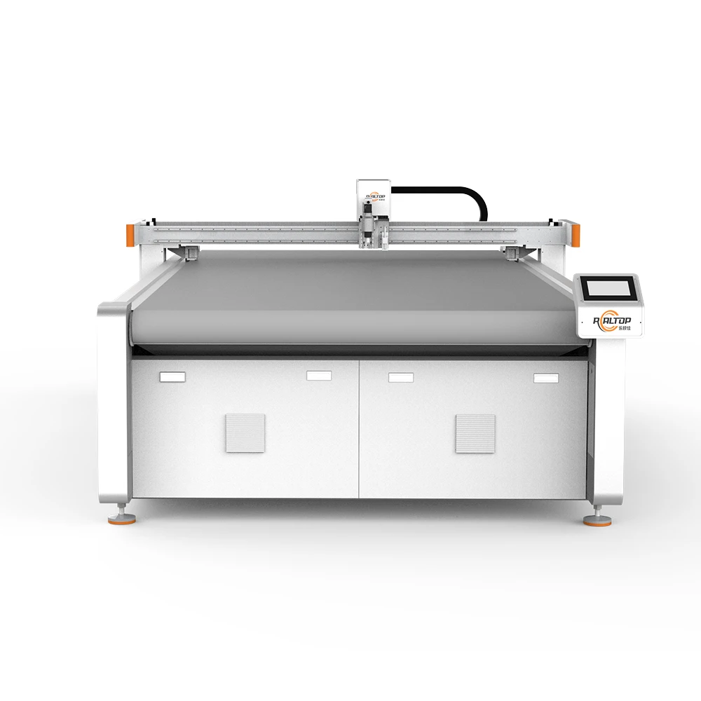
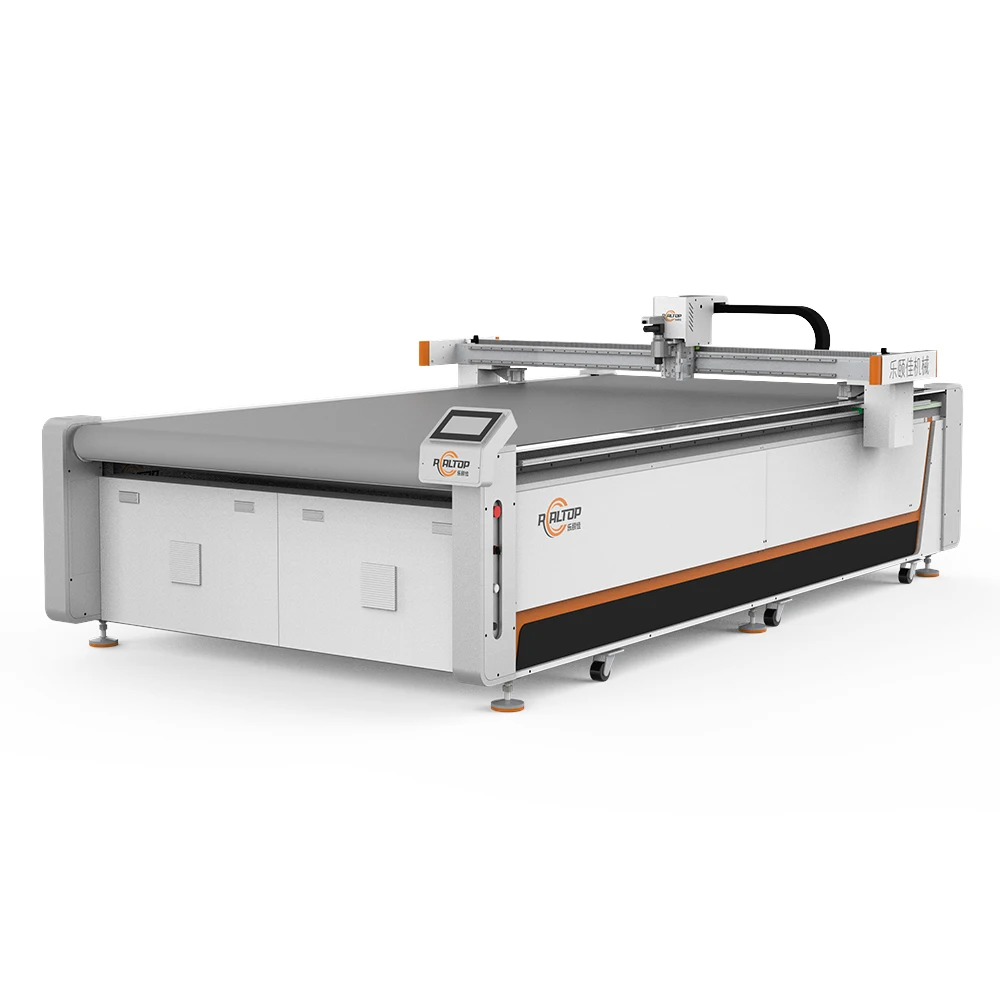
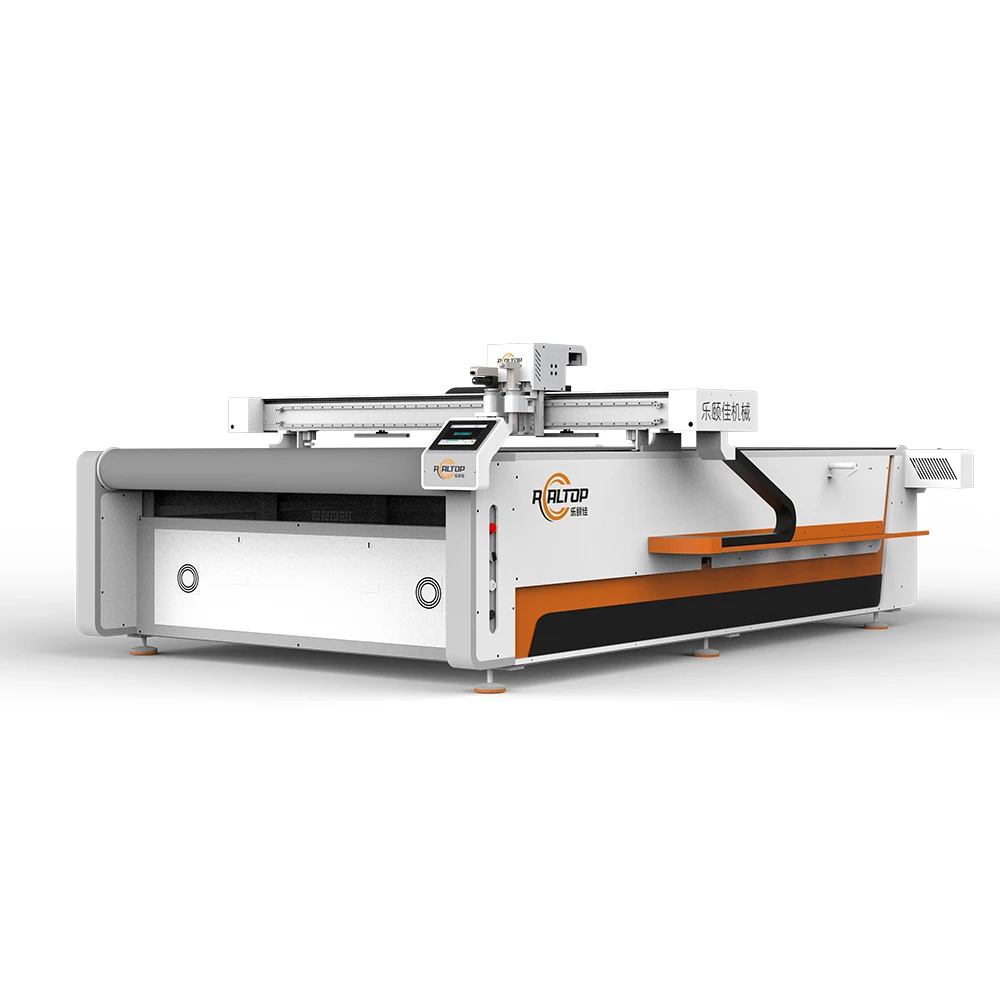
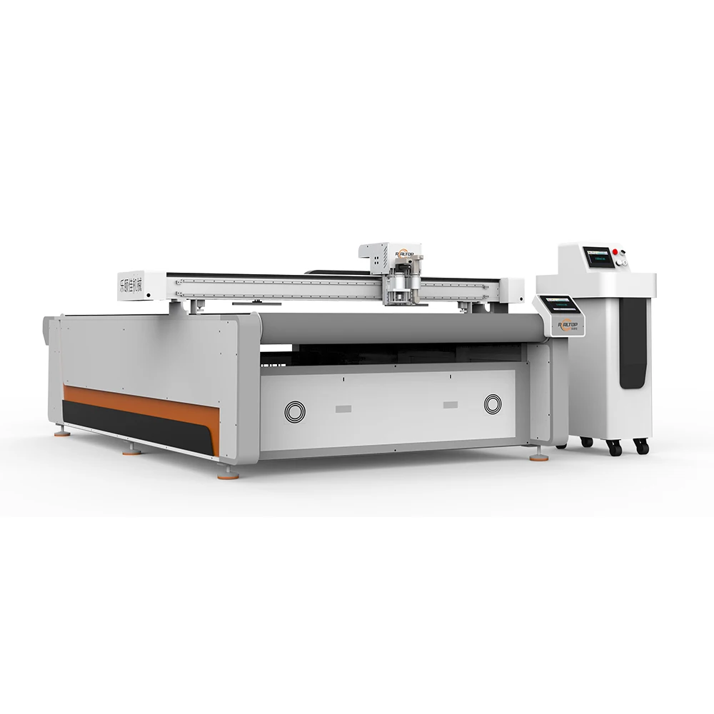
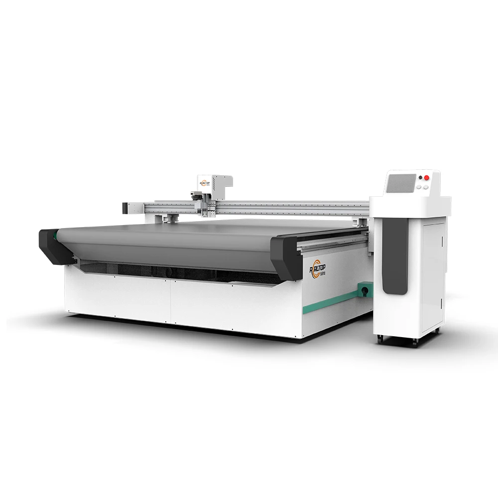
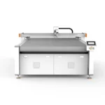
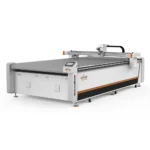
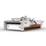
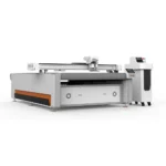
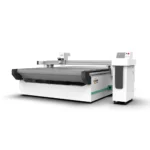
| Product Type | CNC Flat Bed Oscillating Knife Cutting Machine |
| Working Area | 1600×2500 mm |
| Tool Head Options | Oscillating knife, Driven rotary knife, Creasing wheel, Kiss cutting tool, Pneumatic knife, Milling tool, V groove knife |
| Cutting Speed | 0–2000 mm/s |
| Cutting Thickness | ≤ 30 mm (basis not stated in source — confirm material type and density) |
| Cutting / Positioning Accuracy | ±0.1 mm |
| Vacuum Table | Aluminum bellows vacuum table |
| Vacuum Pump Power | 9 kW |
| Servo Motor Options | Panasonic, Delta, Dorna (rated or peak not specified in source) |
| Control System | PLC control panel |
| Voltage Options | 110V / 220V / 380V |
| Software File Formats | PLT, DXF, AI, PDF |
| Nesting Software | Intelligent nesting system with defect avoidance |
| Safety Devices | Infrared sensor device, Emergency stop device |
| Machine Dimensions (L×W×H) | 3300×2100×1350 mm |
| Language Options | English, Russian, Italian, Chinese (custom languages available) |
| Standards | CE |
Application Suitability
| Application | Material or Output |
|---|---|
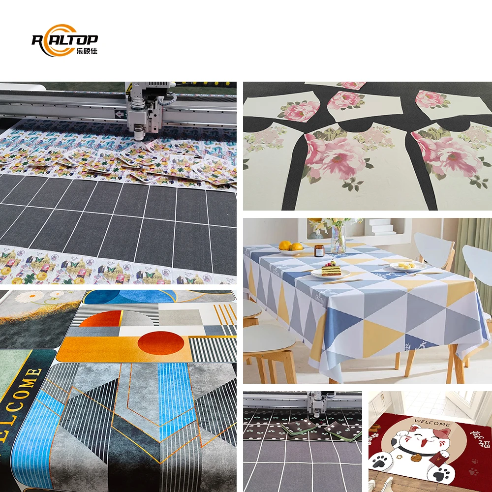
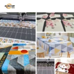
| Apparel manufacturing | Suits, knitwear, lace, complex woven and patterned fabrics |
| Automotive interiors | Seat fabrics, carpets, PVC mats requiring burr-free edges |
| Home textiles | Sofa fabrics, curtains, rugs in single or multi-layer layups |
| Composite processing | Carbon fiber prepreg, aramid, specialty reinforcement materials |
| Flexible material conversion | Leather, foam, cardboard, EVA, PTFE, rubber, acrylic sheets |
Why Specified Cutting Depth Alone Leads to Failed Deliveries
A thickness number without material context is not a specification — it is a guess.
Buyers frequently request a CNC oscillating knife cutting machine specifications sheet and focus on maximum cutting thickness as the primary filter. I have seen orders placed for machines rated at a given depth, only for the buyer to discover on commissioning that the tool head cannot hold an edge on their specific composite layup, or that the vacuum table fails to keep thin knit layers from shifting under lateral blade drag [NEED_CITE: material-specific cutting forces in oscillating knife applications]. The 1625 addresses this by offering seven selectable tool heads, each matched to a different material family, so that how to choose the right configuration becomes a conversation about your actual substrate rather than a single catalog number.
Matching Tool Head Geometry to Substrate Behavior
Selecting between an oscillating knife, a driven rotary knife, and a pneumatic knife is not a matter of preference — each geometry addresses a distinct failure mode in flexible material cutting. The oscillating knife handles dense woven fabrics and multi-layer layups where a drag knife would deflect, while the driven rotary knife suits continuous curved cuts on single-layer knits where edge fraying is the primary concern. The pneumatic knife serves thicker foam and gasket materials where blade withdrawal must be clean to avoid tearing the cut face.
Vacuum Table Zoning and Small-Part Hold-Down
A 9 kW vacuum pump paired with an aluminum bellows table provides the suction volume needed for large-format fabric sheets, but the critical variable for production yield is zoning. When cutting nested garment panels or small automotive interior pieces, the vacuum must be concentrated under the active cutting zone rather than spread across the full 1600×2500 mm bed. Without localized zoning, offcut sections lose adhesion and lift into the blade path, causing edge defects that propagate through the entire nested sheet [NEED_CITE: vacuum table zoning principles for CNC flatbed cutting].
Reading the Parameter Sheet Beyond Working Area
The ±0.1 mm positioning accuracy specification matters most when executing CCD contour recognition on printed textiles, where the camera must track registration marks at production speed and the servo system must translate those coordinates without cumulative drift. Servo motor selection — available in Panasonic, Delta, or Dorna options — directly influences how well the machine maintains this tolerance under sustained high-speed cutting. The PLC control panel processes PLT, DXF, AI, and PDF file formats through the intelligent nesting system, which includes automatic defect avoidance to route cuts around fabric flaws identified during material inspection. Cutting speed ranges from 0 to 2000 mm/s, though achievable speed on any given job depends on material density, layer count, and contour complexity rather than the upper limit alone. Multi-layer cutting capability extends to 30–50 mm thickness depending on fabric type and compression behavior, a range that must be verified on the buyer’s own material sample before configuration is finalized.
What Happens When Configuration Is Skipped
A machine arrives at the buyer’s facility with the wrong creasing wheel installed for their corrugated board grade, and every fold line cracks on the scoring pass. The vacuum table has no zoning valves, so small gasket pieces lift and bunch during cutting, producing scrap that exceeds acceptable waste thresholds. The control language was not confirmed before shipment, and the operator manual does not match the PLC interface language, delaying first production by days while translated instructions are sourced [NEED_CITE: post-shipment configuration mismatches in exported CNC equipment]. These are not hypothetical — they are line items on punch lists I have reviewed after the fact.
Why Source This Platform From REALTOP
In-house design covers both knife and laser cutting technologies within the same engineering team, so material evaluation is not constrained by a single product line. Tool head and table configuration is specified per material sample and production volume rather than selected from a fixed catalog page. CCD camera positioning is validated on the buyer’s printed substrate at speed before the machine leaves the factory. Software compatibility is confirmed against the buyer’s existing PLT, DXF, AI, or PDF workflow before the order is released to production. Voltage, control language, and safety device configuration are locked to the destination market’s electrical standards, not assumed from a default build.
Documentation & Verification
- Machine specification sheet listing confirmed tool head and vacuum table configuration
- Electrical schematic with voltage and frequency matched to destination market
- Sample cutting report executed on buyer-supplied material before order release
- CE declaration referencing applicable machinery directive compliance
- Software licence and file format compatibility note for PLT, DXF, AI, PDF import
- Factory test record documenting positioning accuracy and cutting edge quality
Installation, Commissioning & Support
- 3300×2100×1350 mm footprint requires level concrete floor with clearance for material feed on all sides
- 9 kW vacuum pump and servo drives require dedicated circuit matching confirmed 110V, 220V, or 380V supply
- Machine ships in sectional assembly; table and gantry require on-site alignment and belt tensioning
- First-run commissioning includes vacuum zoning calibration against buyer’s actual sheet size and part geometry
- Operator training covers PLC panel navigation, tool head changeover, and nesting software defect avoidance setup
- Spare parts list covers oscillating knife blades, vacuum seals, and servo motor consumables by part number
Before You Request a Quotation
Provide the material type, layer count or single-sheet thickness, and the largest panel dimension in your current production run. Confirm your facility voltage and frequency, along with the control language your operators require. If your workflow depends on printed contour cutting, share a sample of the printed substrate including the registration mark format so CCD tracking can be evaluated before configuration is finalized.
Frequently Asked Questions
Q: How do I determine which tool head suits my material?
A: Tool head selection depends on material density, thickness, and required edge finish rather than material name alone. An oscillating knife handles dense wovens and multi-layer layups, a driven rotary knife suits single-layer knits with curved contours, and a pneumatic knife addresses thicker foam where clean blade withdrawal prevents face tearing. Sample cutting on your actual material is the only reliable confirmation method.
Q: Will small cut parts stay flat during high-speed cutting?
A: Small-part hold-down depends on vacuum table zoning rather than pump power alone. The aluminum bellows table on this platform supports localized vacuum concentration under the active cutting zone. When configuring the machine, we confirm your smallest part geometry and nest layout so that zoning valves are set to maintain adhesion across the entire cutting sequence without lift or bunching.
Q: What print quality is needed for CCD contour recognition?
A: Reliable CCD tracking at production speed requires printed registration marks with sufficient contrast against the substrate background and consistent mark placement across the sheet. Mark size, color density, and spacing must be evaluated on your actual printed material. We run a tracking test at cutting speed during factory commissioning to confirm the camera can follow your specific print format without missed or misread marks.
Q: How is cutting thickness verified before I commit to an order?
A: Cutting thickness ratings vary with material compression, fiber orientation, and layer adhesion. We request a sample of your production material and run test cuts at the thickness and speed you intend to use. The sample cutting report documents edge quality, dimensional accuracy, and achievable speed so you can evaluate performance against your own quality standards before the machine configuration is finalized.
Q: Will the nesting software work with my existing pattern files?
A: The intelligent nesting system accepts PLT, DXF, AI, and PDF formats and includes automatic defect avoidance for routing cuts around identified fabric flaws. Before the order is released, we confirm file import compatibility using your actual production files and verify that your existing pattern library transfers without geometry loss or layer assignment errors during the nesting process.


商品评价
Clear filtersThere are no reviews yet.