



Fast Shipping
Carrier information

20k products
Payment methods

24/7 Support
Unlimited help desk

2-day Delivery
Track or off orders
Material-Matched Configuration — Tool heads and vacuum zones specified against your fabric weight, leather density or composite layup before the machine leaves the factory, preventing the edge-quality failures we routinely see when buyers select on working area alone.
Technical Specifications
| Parameter | Value |
|---|---|
| Model | 1625(Standard) |
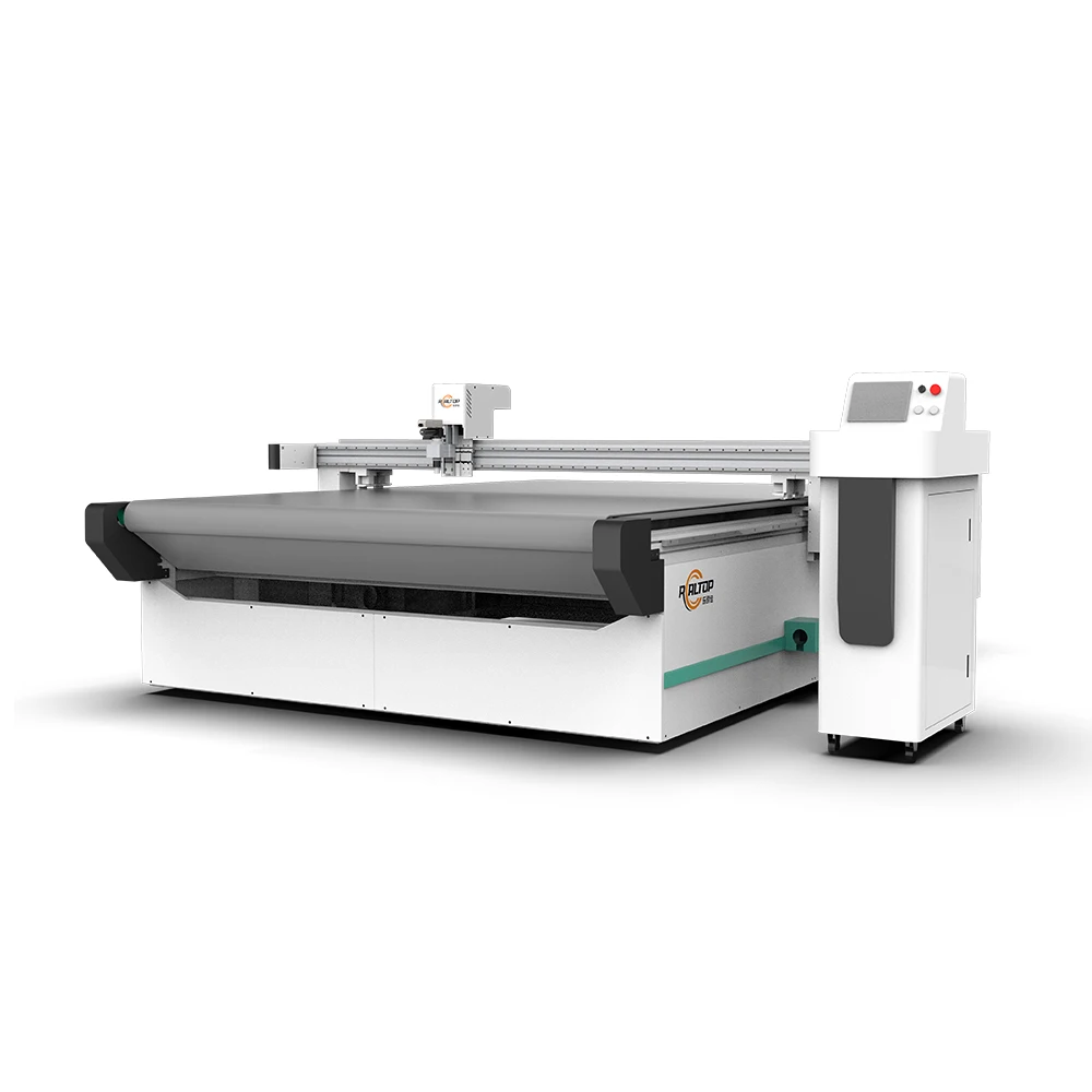
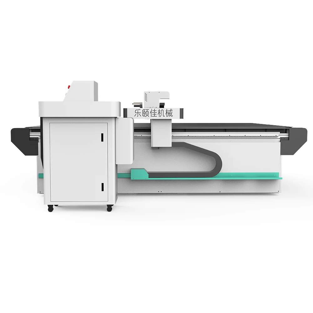
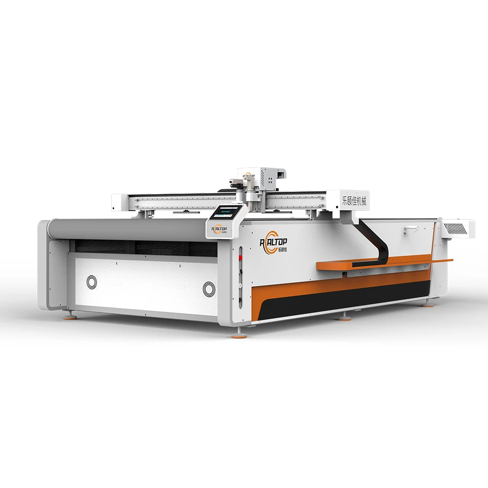
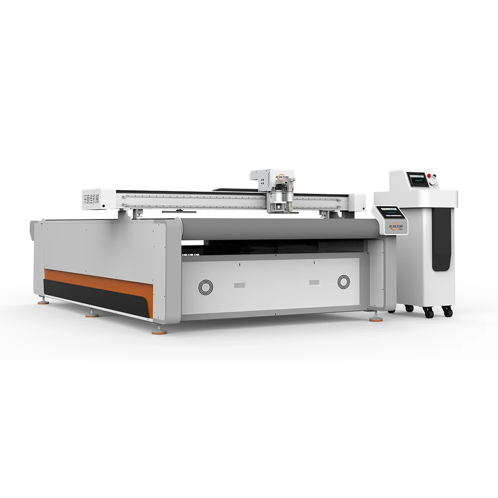
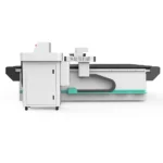
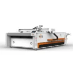
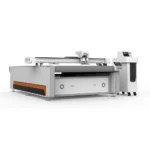
| Product Type | CNC Oscillating Knife Cutting Machine |
| Working Area | 1600×2500 mm |
| Overall Dimensions (L×W×H) | 3300×2100×1350 mm (source value — verify against manufacturer catalog) |
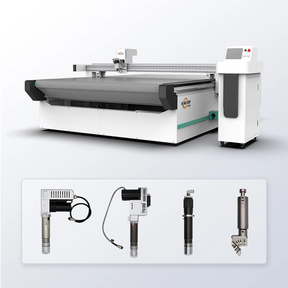
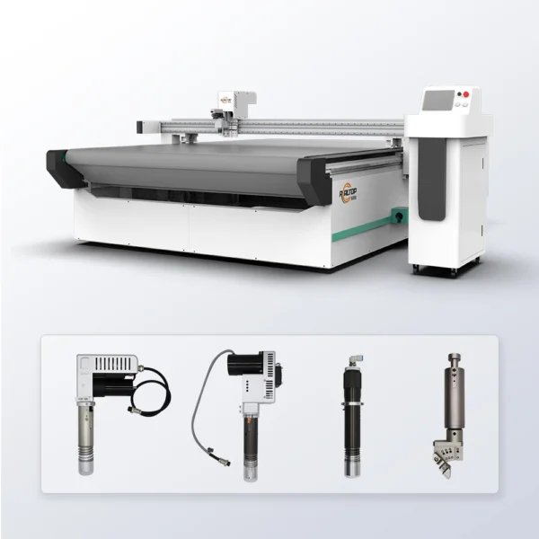
| Tool Head Options | Oscillating knife, Driven rotary knife, Creasing wheel, Kiss cutting tool, Pneumatic knife, Milling tool, V groove knife |
| Cutting Speed | 0-2000 mm/s |
| Cutting Thickness | ≤ 30mm (basis not stated in source — confirm material / thickness) |
| Cutting Accuracy | ±0.1 mm |
| Vacuum Pump Power | 9KW (rated or peak not specified in source) |
| Voltage Options | 110V, 220V, 380V |
| Control System | PLC control panel |
| Vacuum Table Type | Aluminum bellows vacuum table |
| Servo Drive Options | Panasonic, Delta, Dorna (basis not stated in source — confirm standard vs optional) |
| File Formats Supported | PLT, DXF, AI, PDF |
| Contour Recognition | CCD camera positioning |
| Safety Device | Infrared sensor device and emergency stop device |
| Language Options | English, Russian, Italian, Chinese; special languages customizable |
| Standards | CE (source value — verify against manufacturer catalog) |
Application Suitability
| Application | Material or Output |
|---|---|
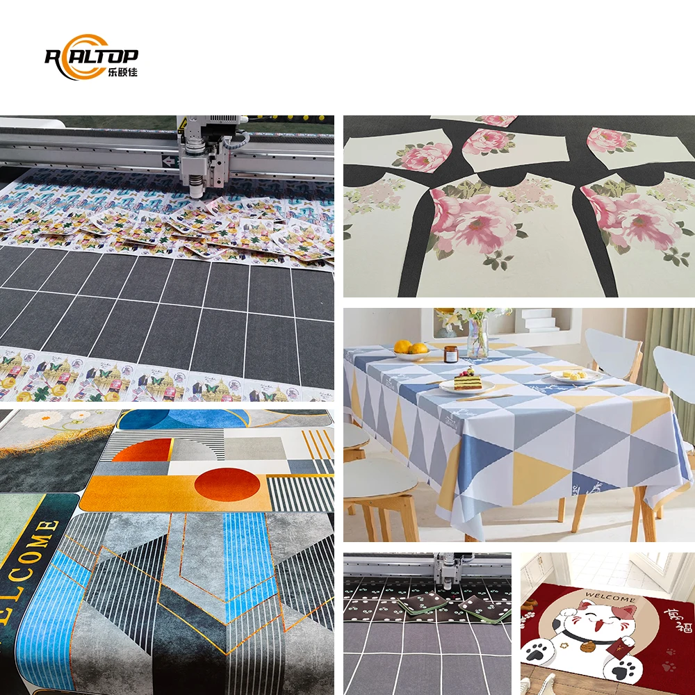
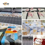
| Garment and Footwear Production | Shoe uppers, apparel patterns, bag components from fabric, leather and synthetic textiles |
| Automotive Interior Manufacturing | Seat covers, car mats, soft trim panels from composite materials and laminated fabrics |
| Packaging Sample Making | Carton prototypes, short-run folding boxes using creasing wheel and kiss cutting configurations |
| Home Furnishing and Soft Goods | Sofa fabrics, lampshades, home composite panels from layered textiles and foam |
| Flexible Material Processing | Printed fabrics, patterned rolls, EPE foam sheets and insulating materials |
What Ragged Edges and Crushed Foam Actually Cost You Beyond the Machine Price
A cutting table that arrives with the wrong tool head for your material turns into a line-stop problem the first week, not a warranty claim months later.
I flew to a roller blind factory in Chile where the buyer had selected the machine purely by working area and nominal thickness capacity. The composite interlayer they ran daily was harder than the standard fabric the configuration was built for. The knife head could not hold the edge through the sandwich structure, leaving frayed margins on every cut piece and forcing a full stop while we shipped a replacement oscillating module across the Pacific. The round-trip airfare and lost production days cost more than the tooling upgrade would have [NEED_CITE: common causes of CNC knife cutting line stoppages in textile and composite workshops]. When evaluating CNC oscillating knife cutting machine specifications, the working area is only the starting point; the tool head and vacuum configuration must be matched to the actual material stack you intend to run.
Tool Head Selection by Material Stack
The 1625 platform supports seven interchangeable tool heads, and the choice between them is never arbitrary. An oscillating knife handles most woven and non-woven fabrics cleanly, while a driven rotary knife suits continuous roll cutting where the material feeds without pause. For corrugated or laminated board used in packaging samples, the creasing wheel and V groove knife produce fold lines without tearing the outer face. Selecting the correct head depends on the material tensile strength, layer count and whether the cut edge will be visible on the finished product.
Vacuum Table Zoning for Small Part Retention
The aluminum bellows vacuum table delivers adsorption across the full 1600×2500 mm surface with a flatness tolerance that keeps thin fabrics and flexible composites from shifting during high-speed passes. This matters most when nesting small pattern pieces — shoe upper components or automotive trim segments — where insufficient hold-down allows the leading edge to lift ahead of the knife, producing dimensional drift that only shows up during assembly [NEED_CITE: vacuum table flatness requirements for precision fabric cutting]. Zoning confirmation before order ensures the suction distribution matches your typical nest layout rather than a generic test sheet.
Specification Interpretation for Production Reality
The stated cutting accuracy of ±0.1 mm across the full working area relies on the servo drive maintaining positional integrity at the selected cutting speed of up to 2000 mm/s. In practice, this tolerance holds on stable materials like leather and dense woven fabric; compressible foams and loosely layered composites introduce material deflection that the machine cannot compensate for mechanically. The ≤30mm cutting thickness rating applies to specific material densities and must be verified against your actual stock — a 30mm block of EPE foam presents a completely different cutting resistance than a 30mm stack of bonded leather offcuts. The CCD camera positioning system tracks printed registration marks for contour work on patterned rolls, but its tracking reliability at full production speed depends on mark contrast, lighting conditions and the camera’s frame rate relative to table travel speed. Voltage configuration — available as 110V, 220V or 380V — must match the facility supply before the control cabinet is wired, not after arrival.
The Hidden Cost of Skipping the Material Trial
Buyers who approve a configuration based on the supplier’s standard test material — typically a mid-weight woven fabric — encounter problems the moment their actual production stock reaches the table. Foam cores with adhesive interlayers behave differently under the knife than homogenous foam of the same thickness. Printed contour work that tracks perfectly on high-contrast test sheets may fail to register on low-saturation prints running at full speed. These mismatches surface during the first production run, not during factory acceptance testing on generic samples [NEED_CITE: material-dependent cutting performance variation in oscillating knife systems]. A sample cutting report on your own material, covering edge quality, dimensional accuracy and CCD tracking at intended production speed, costs nothing compared to a transatlantic service flight.
Why This Configuration Approach Works
In-house design covering both the knife cutting head mechanics and the vacuum table engineering means the tool load and hold-down force are balanced as a system, not specified independently. The aluminum bellows table construction provides the flatness baseline that the ±0.1 mm positional accuracy depends on, rather than treating the table as a commodity platform beneath a precision drive. CCD camera integration is confirmed against your actual print files before the machine ships, not left as a commissioning-day surprise. Voltage, control language and software file format compatibility — PLT, DXF, AI, PDF — are locked in at order confirmation so the PLC panel and nesting software match the operator’s environment from day one.
Documentation & Verification
- Machine specification sheet listing confirmed tool head and vacuum zone configuration for your material
- Electrical schematic with voltage, phase and circuit breaker ratings matching your facility supply
- Sample cutting report on your fabric, leather or composite stock with edge photographs and dimensional readings
- Software licence note confirming file format compatibility with your existing nesting workflow
- Spare parts list identifying consumable blades, vacuum seals and CCD calibration targets
- Factory test record documenting cutting accuracy verification before crating
Installation, Commissioning & Support
- Level floor requirement across the 3300×2100 mm footprint to maintain vacuum seal and positional accuracy
- Dedicated circuit for the 9KW vacuum pump separate from the PLC control panel supply
- Single-piece frame delivery requiring overhead clearance for placement in the production area
- First-run parameter tuning for oscillation frequency and knife depth against your specific material stack
- Operator training on tool head changeover and CCD camera mark teaching for new print patterns
- Consumable blade inventory and vacuum table seal replacement schedule documented at handover
What We Need to Quote Your Configuration
Send us the material type, thickness range and typical sheet or roll dimensions you plan to run daily. Include a sample of your print file if CCD contour recognition is required, along with your facility voltage and preferred control language. We will return a tool head recommendation and vacuum zone layout matched to that input, followed by a cutting trial on your actual material before any order commitment.
Frequently Asked Questions
Q: How do I determine which tool head my material requires?
A: The correct tool head depends on material tensile strength, layer structure and whether the cut edge is visible on the finished product. Oscillating knives suit most woven fabrics and leather, driven rotary knives handle continuous roll feeds, and creasing wheels address packaging board. Submit your material sample for a cutting trial that tests edge quality and dimensional accuracy under production-speed conditions before the configuration is finalized.
Q: What does the ≤30mm cutting thickness rating actually mean for my material?
A: That rating applies to a specific material density that may not match your production stock. A 30mm EPE foam block cuts differently than a 30mm bonded leather stack due to internal layer adhesion and compression behaviour. Provide your exact material for a cutting test that confirms achievable thickness, knife pass count and edge condition under the tool head selected for your application.
Q: How do I verify CCD contour recognition will work on my printed fabrics?
A: Tracking performance depends on registration mark contrast, print saturation and the camera frame rate relative to table travel speed. Request a sample cutting report using your actual printed material, showing contour accuracy measured at your intended production speed rather than a slow-speed demonstration. This confirms the system reads your marks reliably before the machine is shipped.
Q: Why does vacuum table zoning matter for small fabric parts?
A: Small nested components — shoe upper pieces or automotive trim segments — require localized suction to prevent leading-edge lift ahead of the knife during high-speed passes. Insufficient zone coverage causes dimensional drift that appears only during assembly. Confirm the zone layout against your typical nesting pattern to ensure hold-down force where your smallest parts sit on the table surface.
Q: How are software compatibility and control language confirmed before order?
A: File format support — PLT, DXF, AI, PDF — must align with your existing nesting software and design workflow. Control language options include English, Russian, Italian and Chinese with additional languages available on request. These specifications are locked at order confirmation alongside voltage and plug type so the PLC panel and software environment match your operator requirements from the first production shift.


商品评价
Clear filtersThere are no reviews yet.