

Fast Shipping
Carrier information

20k products
Payment methods

24/7 Support
Unlimited help desk

2-day Delivery
Track or off orders
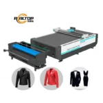
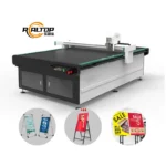
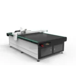
Tool Head Matching — oscillating, drag, circular and pneumatic knife options configured per material to prevent ragged edges before the first cut.
Technical Specifications
| Parameter | Value |
|---|---|
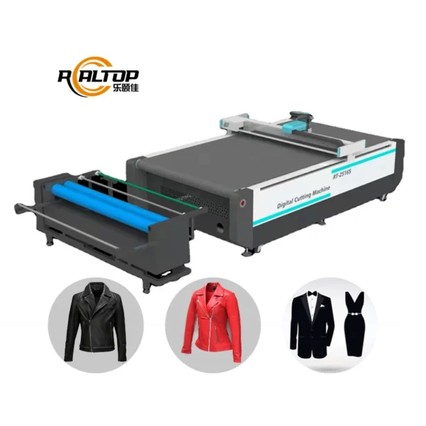
| Product Type | CNC Oscillating Knife Cutting Machine |
| Model | RT-D2516/RT-S2516 |
| Working Area | 1600 × 2500 mm |
| Machine Size | 3450 × 2300 × 1250 mm |
| Rated Power | 9 kW |
| Translational Velocity | 800–1200 mm/s |
| Cutting Thickness Range | 20–80 mm (basis not stated in source — confirm material, density and layer count) |
| Repeated Accuracy | ≤0.1 mm |
| Transmission System | Digital servo motor, linear guide, synchronous belt, ball screw |
| Servo Motor | Delta servo motor |
| Linear Rail | Taiwan Hiwin rail |
| Vacuum Pump | 7.5 kW |
| Working Table | Flatbed with vacuum adsorption, Germany imported conveyor belt, auto feeding |
| Tool Head Options | Oscillating knife, pneumatic knife, high-power vibrating knife, circular knife, V-cutting knife, drag knife, creasing wheel, dotted line knife, punching, brush |
| Multifunctional Head | Swiss imported knife with vibration full cutting, vibration half cutting, cursor location |
| Visual Positioning | Small CCD camera mark point positioning, panoramic camera recognition, projection positioning |
| Safety Devices | Infrared sensors, anti-collision, emergency stop |
| Instruction System | HP-GL compatible format |
| Voltage | 380V ± 10% |
Application Suitability
| Application | Material or Output |
|---|---|
| Garment and footwear cutting | Multi-layer woven fabric, knit fabric, denim, leather, synthetic leather |
| Automotive interior trimming | Carpet, upholstery fabric, gasket material, sound-deadening composite |
| Bag and luggage production | PU, EVA, PVC sheets, sponge composite leather |
| Soft home furnishings | Curtain fabric, upholstery textile, cushion foam layers |
| Sports and outdoor gear | Neoprene, technical textile, coated fabric |
| Graphic advertising and printing | Vinyl, banner material, printed contour substrates |
Why Ragged Edges Appear on Coated and Composite Fabrics
The cutting tool was specified for the sample, not for the real production material.
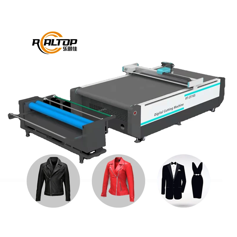
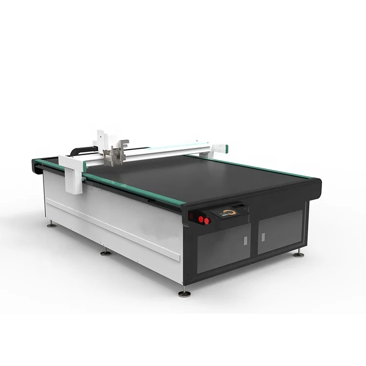
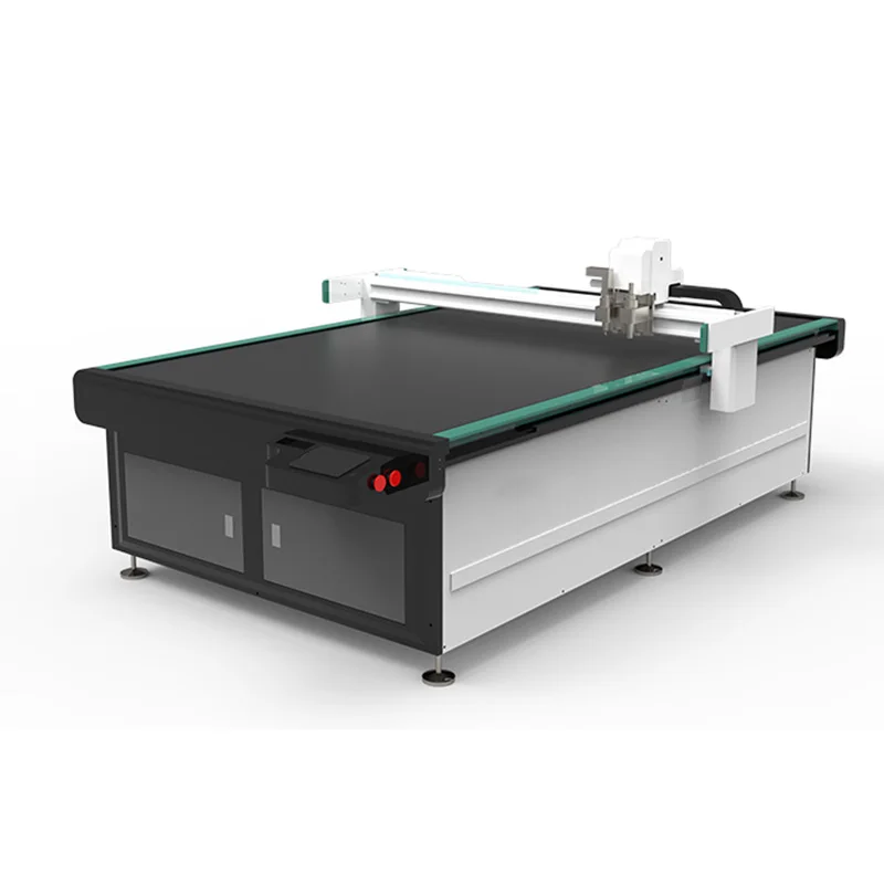
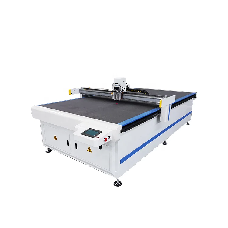
When a buyer sends standard cotton for testing but runs coated functional fabric or sponge composite leather on the shop floor, the oscillating frequency and blade geometry that worked perfectly on the sample will shred the coating or crush the foam core. I have seen cutting lines forced to halve their speed just to keep edge quality acceptable, and that lost throughput is rarely recovered. The RT-D2516/RT-S2516 CNC oscillating knife cutting machine for fabric and leather addresses this by offering ten tool head options, each matched to the buyer’s actual material stack before the machine ships [NEED_CITE: material-specific tool head selection for flexible composite cutting].
Oscillating Knife Mechanics on Flexible Textiles
Flexible materials shift, wrinkle and bunch under lateral blade pressure. The Swiss imported oscillating knife head on the RT-D2516/RT-S2516 moves vertically at high frequency, slicing through fabric plies with minimal horizontal drag. This matters most on slippery synthetics and multi-layer layups where a drag knife would pull the top ply out of register. Repeated accuracy holds at ≤0.1 mm across the 1600 × 2500 mm working area, which keeps pattern pieces within garment assembly tolerance even on long production runs.
Vacuum Zoning and Small-Part Stability
A flatbed cutting table with full-sheet vacuum suction works fine until the pattern nests dozens of small pieces. Once the knife cuts through, individual parts lose their surrounding material and can lift under blade friction. The 7.5 kW vacuum pump on this CNC oscillating knife cutting machine for fabric and leather provides enough suction to hold small cut pieces flat, and the flatbed table can be configured with zone control so vacuum concentrates where parts are smallest [NEED_CITE: vacuum adsorption zoning principles for CNC flatbed cutting tables]. The Germany imported conveyor belt and auto-feeding system then advance the material for the next layup without manual repositioning.
Translational Speed, Servo Drive and Edge Quality
The Delta servo motor and Taiwan Hiwin linear rail combination allows translational velocity between 800 and 1200 mm/s. Speed alone does not determine output; the servo response must also decelerate precisely at contour corners to maintain ≤0.1 mm repeated accuracy. On garment patterns with tight curves — armholes, collar contours, pocket shapes — the digital servo motor and synchronous belt transmission keep the knife path tight rather than overshooting. The result is a cut edge that does not require secondary trimming before sewing.
CCD Contour Recognition on Printed Textiles
For printed fabrics where the cut path must follow a registration mark rather than a digital file coordinate, the CCD camera system offers two modes: small mark point positioning and panoramic camera recognition. The small CCD tracks discrete printed marks, while the panoramic camera reads the entire printed contour across the working area. Projection positioning provides a third option for operators who need to visually confirm cut paths before the knife engages. These three visual positioning methods are selectable per job, so a single machine handles both solid-color layups and printed contour work without retooling.
The Cost of Skipping Material-Specific Testing
When the tool head is chosen from a catalogue rather than matched to the buyer’s real material, the consequences compound. A pneumatic knife designed for dense leather will crush a three-layer sponge composite, producing a beveled edge that fails downstream assembly inspection. A circular knife set for high speed will melt the coating on PVC-backed fabric. I have watched buyers discover these mismatches only after installation, when the entire cutting line becomes a bottleneck. Correcting the problem after shipment means ordering a new tool head, waiting for delivery, and absorbing the downtime [NEED_CITE: post-installation tooling reconfiguration costs in textile cutting operations].
Why the Configuration Workflow Matters Here
In-house design and production of both knife and laser cutting systems means the cutting method itself is part of the specification conversation, not assumed. Tool head and vacuum table zoning are configured per material and per production volume before the order is finalized. CCD camera positioning capability is confirmed against the buyer’s specific printed mark geometry. Software file format compatibility — HP-GL and the buyer’s existing nesting workflow — is verified before production starts. Sample cutting on the buyer’s own material is conducted before commitment, producing a documented report on edge quality and achievable cutting depth.
Documentation & Verification
- Factory test record run on your specific fabric type and layer count before dispatch
- Tool head and vacuum zone configuration list matched to your material thickness
- Electrical schematic with 380V ± 10% confirmation and control language noted
- Sample cutting report on buyer-supplied material documenting edge quality and depth
- Software licence and HP-GL file format compatibility note included
- Spare parts list covering blades, vacuum seals and conveyor belt segments
Installation, Commissioning & Support
- 3450 × 2300 mm footprint requires level concrete floor with clearance for auto-feeding infeed and outfeed
- 9 kW rated power plus 7.5 kW vacuum pump need dedicated 380V ± 10% three-phase circuit
- Machine ships with flatbed table pre-assembled; conveyor belt and auto-feeder attached on site
- First-run calibration covers servo tuning, vacuum zone mapping and CCD mark registration
- Operator training includes tool head changeover procedure for oscillating, drag and circular knife
- Daily maintenance checklist covers Hiwin rail lubrication, blade inspection and vacuum filter cleaning
What to Include in Your Inquiry
Send the actual material you will be cutting — type, thickness, number of layers, and whether it has a coating or composite backing. Confirm your local voltage and frequency so the electrical system is built to match, and specify the control language your operators need. If your nesting software exports to a format other than HP-GL, include a sample file so compatibility is confirmed before the machine enters production.
Frequently Asked Questions
Q: How is cutting thickness capacity verified for my specific material and layer count?
A: The 20–80 mm range is a general guide; actual capacity depends on material density, layer count and tool head selection. We run a sample cut on your exact material stack, document the achievable depth and edge quality, and confirm the tool head and oscillation frequency before the order is finalized.
Q: Which tool head is right for my material — oscillating, drag or circular knife?
A: Oscillating knife suits multi-layer fabric and composite materials where lateral drag would shift plies. Drag knife works on thin vinyl and single-ply leather. Circular knife handles straight cuts on thicker foam. We match the head to your material during the sample cutting stage.
Q: Can the CCD camera track my printed registration marks at full production speed?
A: Both the small CCD mark point system and the panoramic camera are designed to operate at production translational velocity. We verify recognition accuracy against your specific print mark size, contrast and spacing during pre-shipment testing on your printed material sample.
Q: Is the vacuum table zoning adequate for my small-part nesting patterns?
A: The 7.5 kW vacuum pump provides sufficient holding force across the 1600 × 2500 mm table. Zone configuration is planned around your nesting layout so that small parts remain flat after cut-through. We review your typical pattern file before finalizing the table setup.
Q: What software file formats does the system accept from my nesting workflow?
A: The instruction system is HP-GL compatible. If your nesting software exports to DXF, PLT or another vector format, we confirm file import and path interpretation during the specification stage so your existing workflow connects without manual file conversion.


商品评价
Clear filtersThere are no reviews yet.