



Fast Shipping
Carrier information

20k products
Payment methods

24/7 Support
Unlimited help desk

2-day Delivery
Track or off orders
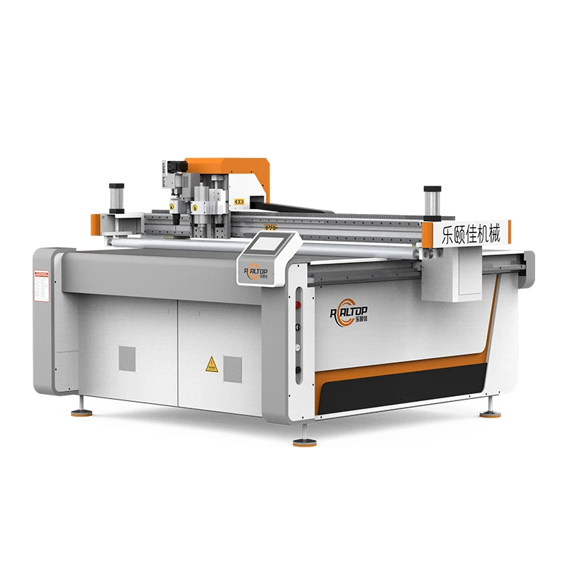
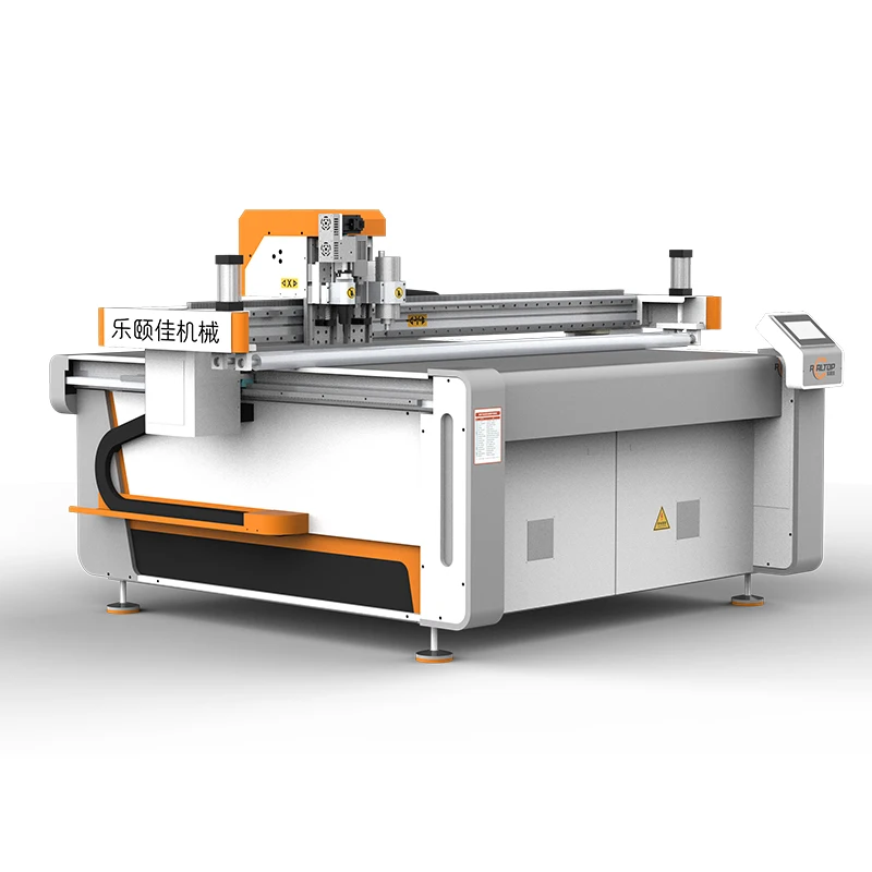
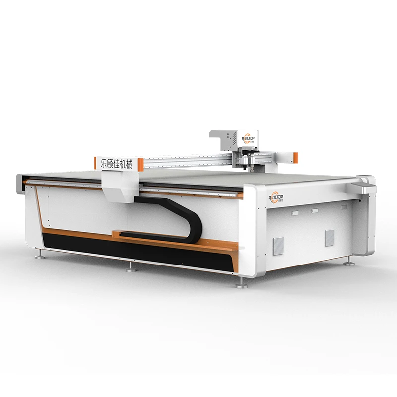
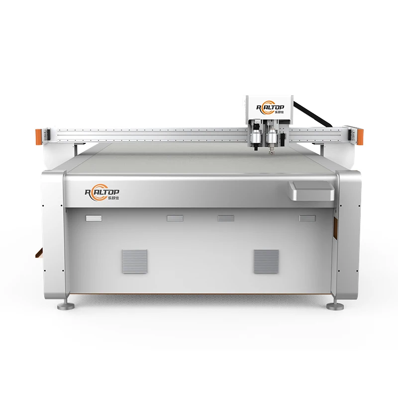
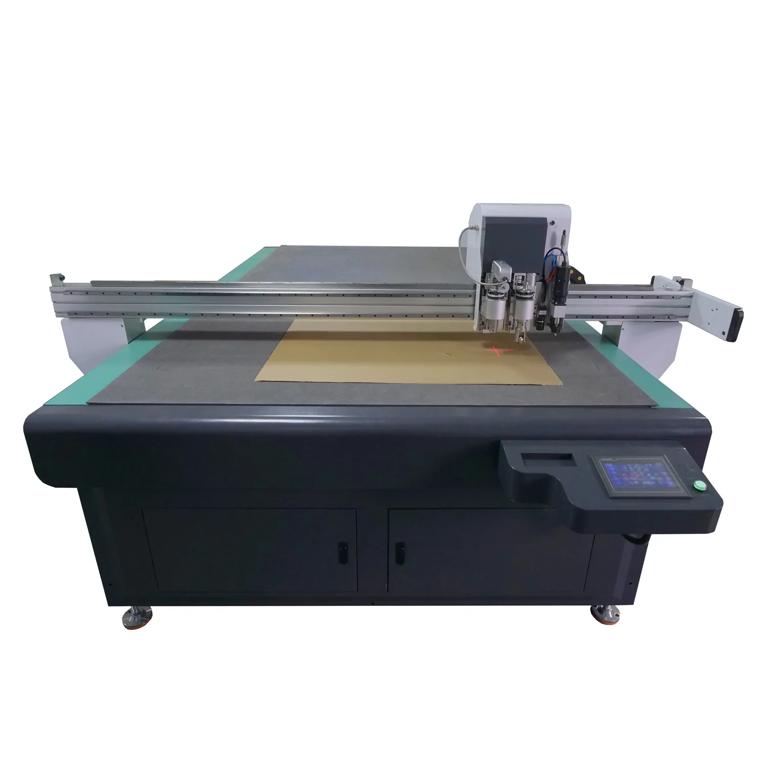
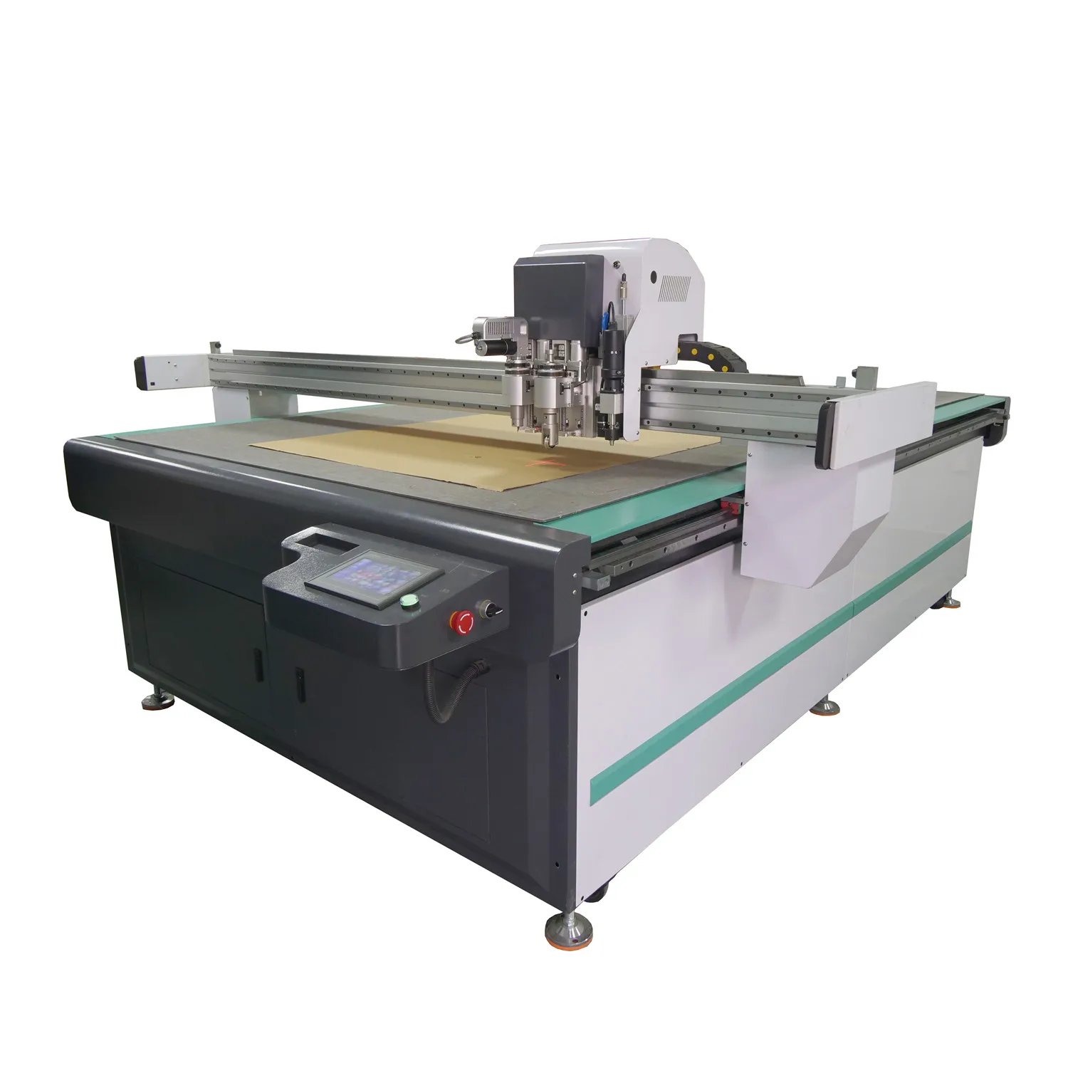
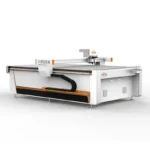
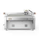
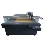
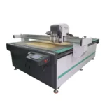
Tool head and table configuration specified per material and production volume — the RT-D2516 / RT-S2516 CNC Oscillating Knife Cutting Machine is configured only after the buyer’s material thickness, density, and daily cutting profile are confirmed, ensuring knife type, cutting depth, and vacuum zoning match real production rather than generic assumptions.
Technical Specifications
| Parameter | Value |
|---|---|
| Model | RT-D2516 / RT-S2516 |
| Product Type | CNC Oscillating Knife Cutting Machine |
| Working Area | 1600 × 2500 mm |
| Machine Size (Overall Dimensions) | 3450 × 2300 × 1250 mm |
| Rated Power | 9 kW |
| Voltage | 380V ±10% (frequency 50Hz / 60Hz to be confirmed before shipment) |
| Transmission System | Digital servo motor, linear guide, synchronous belt, ball screw (imported) |
| Servo Motor Brand Options | Delta (Taiwan) or Panasonic (Japan) |
| Cutting Speed (Translational Velocity) | 800–2000 mm/s |
| Cutting Speed (Material Dependent) | 200–800 mm/s (basis not stated in source — confirm material type and thickness) |
| Maximum Cutting Thickness | ≤100 mm (varies by material density and hardness) |
| Repeatability | ≤0.1 mm |
| Table Type Options | Flat working table or Auto-feeding table |
| Vacuum Table Surface | Magnesium-aluminum alloy platform, PVDF powder spraying, anodic oxidation |
| Vacuum Pump | 7.5 kW, aviation aluminum shell with built-in silencer |
| Multifunctional Head Options | Oscillating knife, pneumatic knife, high-power vibrating knife, circular knife, V-cutting knife, drag knife, creasing wheel, dotted line knife, punching tool, Swiss imported knife, brush |
| Visual Positioning Options | Small CCD camera mark point positioning, panoramic camera recognition, projection positioning |
| Control System | HP-GL compatible format |
| Software | Auto nesting; supports PLT, DXF, AI file formats |
| Touch Screen Control Panel | English, Russian, Italian, Chinese (other languages customizable) |
| Safety Devices | Infrared induction blocking, anti-collision sensors (both sides of beam), emergency stop button |
| Standards | CE declaration where applicable (verify per order) |
Application Suitability
| Application | Material or Output |
|---|---|
| Packaging & carton sample making | Corrugated cardboard, honeycomb cardboard, grey board — full cut, crease, and V-groove on one table |
| Leather & footwear production | Natural leather, synthetic PU, shoe upper material — multi-layer nesting for yield optimization |
| Gasket & sealing fabrication | Rubber, PTFE, ETFE, non-asbestos fiber — oscillating or pneumatic knife matched to Shore hardness |
| Composite & foam processing | EVA, XPE, sponge, PU foam board — high-power vibrating knife to prevent edge crush |
| Advertising & signage | PVC foam board, sticker film, vinyl — drag knife and contour cut with CCD registration |
Why a Machine Picked by Working Area Alone Fails on the First Production Run
A cutting table specified only on bed size will almost always mismatch the tool head to the actual material.
I worked with a packaging sample maker in Jinan who sourced a flatbed cutter based purely on the 1600 × 2500 mm envelope. The first batch of grey board samples came back with torn V-groove edges because the material density was nearly double what the standard oscillating knife was set up for. Two sample batches were scrapped before the tool head was swapped and the vacuum zoning was reconfigured for smaller carton blanks. [NEED_CITE: material density variation across corrugated and grey board grades]
When buyers evaluate a CNC Oscillating Knife Cutting Machine on working area alone, the cutting speed, edge quality, and vacuum holding force are left to chance. The real specification gap is between the machine’s configured tool head and the buyer’s actual material stack — thickness, density, surface finish, and whether the job requires full cut, half cut, creasing, or grooving in the same cycle.
Matching Tool Head to Material Instead of Forcing One Blade Through Everything
The multifunctional head on the RT-D2516 / RT-S2516 accepts a range of interchangeable tooling — oscillating knife, drag knife, V-cutting knife, creasing wheel, pneumatic knife, and punching tool among them. This means a single cutting table can move from full-depth oscillating cuts on dense corrugated board to creasing wheel passes for fold lines without re-fixturing the sheet. Selecting the correct knife amplitude and blade geometry for each material prevents the edge crush and fiber tear that plague generic setups.
Vacuum Zoning That Holds Small Blanks Flat Without Manual Taping
The magnesium-aluminum alloy vacuum table uses PVDF powder coating and anodic oxidation for a flat, wear-resistant surface. A 7.5 kW pump with integrated silencer provides consistent suction across the bed. For packaging sample work, where carton blanks can be small and irregular, zone isolation on the vacuum table determines whether parts stay pinned during high-speed cutting or lift at the edges. Confirming zone layout before order prevents the situation where a table that holds full sheets perfectly still fails on nested small blanks.
Reading the Spec Sheet Against Actual Production Needs
The ≤0.1 mm repeatability is achieved through imported ball screws, linear guides, and the choice between Delta or Panasonic digital servo motors — this matters when a packaging sample requires multiple tool passes (cut, crease, perforate) on the same sheet and every pass must register to within a fraction of a millimeter. The cutting speed range of 800–2000 mm/s translational velocity sets the traverse rate, but actual material cutting speed drops to 200–800 mm/s depending on stock density and thickness. The maximum cutting thickness of ≤100 mm is material-dependent; a dense grey board and a soft EVA foam of the same thickness demand entirely different knife types, amplitudes, and vacuum settings. [NEED_CITE: relationship between servo resolution and multi-pass registration accuracy in flatbed cutting]
What Happens When the Configuration Guess Is Wrong
Choosing a standard oscillating knife for high-density grey board produces ragged V-grooves and crushed edges. Running a drag knife on foam compresses the material instead of cutting it cleanly. Setting vacuum zones too large for small gasket blanks causes part lift mid-cut, destroying nesting yield. [NEED_CITE: common causes of edge quality failure in digital flatbed knife cutting]
These are not machine defects. They are specification gaps — the distance between a generic configuration and what the buyer’s material actually requires.
Why the Configuration Conversation Happens Before the Quotation Here
In-house design covers both knife and laser cutting technologies, so the cutting method itself is matched to the material rather than forcing one method across all jobs. Tool head and table configuration are specified per material type and production volume, documented in a written configuration list before the order is placed. CCD camera positioning — small mark point, panoramic recognition, or projection — is confirmed against the buyer’s printed contour work. Software compatibility with the buyer’s existing PLT, DXF, or AI workflow is verified before commitment. Voltage, plug type, and control panel language are locked in writing prior to shipment, not discovered when the crate arrives.
Documentation & Verification
- Machine specification sheet confirming all tool heads and table zones included in your order
- Electrical schematic with voltage, frequency, and plug type confirmed for your facility
- Sample cutting report on your own material showing edge quality and achievable thickness
- Tool head and table configuration list mapping each tool to its intended material and cut type
- Software licence and file format compatibility note for PLT, DXF, and AI nesting workflows
- Factory test record documenting repeatability and cutting performance before dispatch
Installation, Commissioning & Support
- 9 kW rated power requires a dedicated 380V circuit with confirmed 50Hz or 60Hz frequency at your site
- Machine footprint of 3450 × 2300 mm demands clear floor space plus operator access on three sides
- Assembly state to be confirmed (CBU or SKD) before shipment to plan receiving equipment
- First-run commissioning includes tool head calibration, vacuum zone mapping, and servo tuning for your material
- Touch screen control panel language set to your operator preference before delivery
- Spare parts list covering blades, vacuum seals, and wear items specific to your configured tool heads
What We Need to Configure Your Machine Correctly
Send a sample of the material you cut most often — including the actual thickness and density, not just the product name. Tell us which cut types your jobs require (full cut, half cut, crease, V-groove, perforation) and what your typical sheet size and daily volume look like. Confirm your facility voltage, frequency, and the file formats your design team currently works in so the software and nesting workflow are validated before the machine ships.
Frequently Asked Questions
Q: How do I select the right tool head for my material?
A: Each material responds differently — dense corrugated board needs a high-amplitude oscillating knife, while soft foam requires a different blade geometry to avoid edge crush. We test your actual material before specifying the tool head, then document the configuration so every tool is mapped to its intended material and cut type.
Q: What determines the actual cutting thickness I can achieve?
A: The ≤100 mm maximum depends entirely on material density and hardness. A soft EVA foam cuts cleanly at much greater thickness than a dense grey board. We run your specific material on the RT-D2516 / RT-S2516 and record achievable thickness and edge quality in the sample cutting report before you commit.
Q: Will small parts stay fixed during cutting on the vacuum table?
A: Small nested blanks require proper vacuum zone isolation. The 7.5 kW pump and zoned magnesium-aluminum table are configured based on your typical part size. We confirm zone layout against your nesting patterns so parts remain pinned without manual taping during high-speed cuts.
Q: Can the CCD system track printed contours at production speed?
A: The RT-D2516 / RT-S2516 offers three visual positioning options — small CCD mark point, panoramic recognition, and projection. Stability at production speed depends on print mark contrast and sheet registration. We test with your printed material to verify tracking reliability at your target cutting speed.
Q: Will the nesting software work with my existing design files?
A: The auto nesting software accepts PLT, DXF, and AI formats. We verify compatibility with your current CAD workflow and file versions before order confirmation, and provide a written compatibility note so there are no surprises when your operators start importing jobs.


商品评价
Clear filtersThere are no reviews yet.