


Fast Shipping
Carrier information

20k products
Payment methods

24/7 Support
Unlimited help desk

2-day Delivery
Track or off orders
Material-Matched Tooling — The in-house design team pairs oscillating knife, drag knife and vacuum table zoning specifically to your fabric, leather or composite sheet rather than forcing one setup across every job.
Technical Specifications
| Parameter | Value |
|---|---|
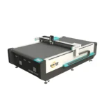
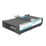
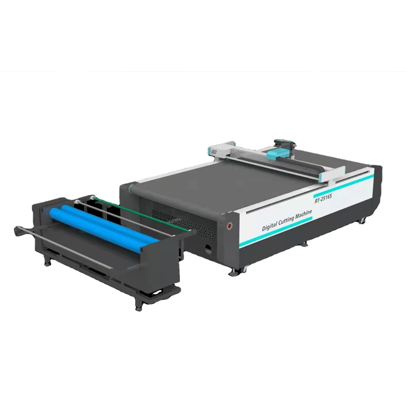
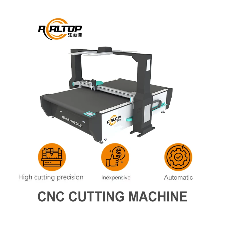
| Product Type | CNC Auto Feed Oscillating Knife Cutting Machine |
| Model | RT-D2516/RT-S2516 |
| Working Area | 1600 × 2500 mm |
| Machine Size | 3450 × 2300 × 1250 mm |
| Rated Power | 9 kW |
| Vacuum Pump | 7.5 kW |
| Cutting Thickness | Up to 50 mm depending on material density |
| Translational Velocity | 800–1200 mm/s |
| Repeated Accuracy | ≤ 0.1 mm |
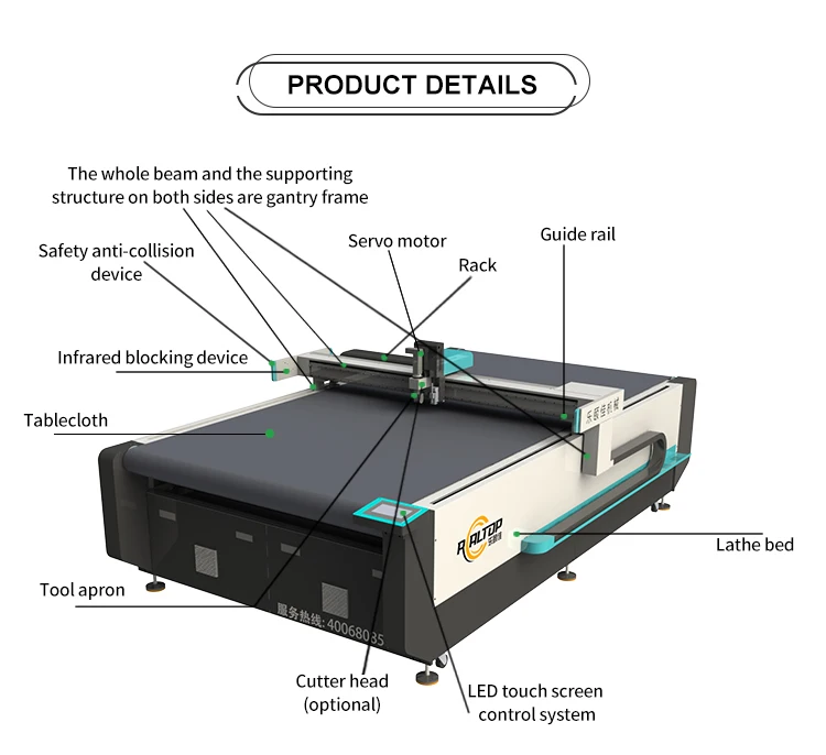
| Transmission System | Digital servo motor, linear guide, synchronous belt, ball screw |
| Linear Rail | Taiwan Hiwin |
| Conveyor Belt | Germany imported |
| Table Cloth | High-density felt |
| Safety Device | Infrared sensors |
| Instruction System | HP-GL compatible format |
| Voltage | 380 V ± 10 % |
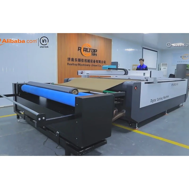
| Tool Compatibility | Round knife, marking pen, auto feeder |
| Software Language Options | English, Russian, Italian, Chinese; special languages customizable |
| Certification | CE |
Application Suitability
| Application | Material or Output |
|---|---|
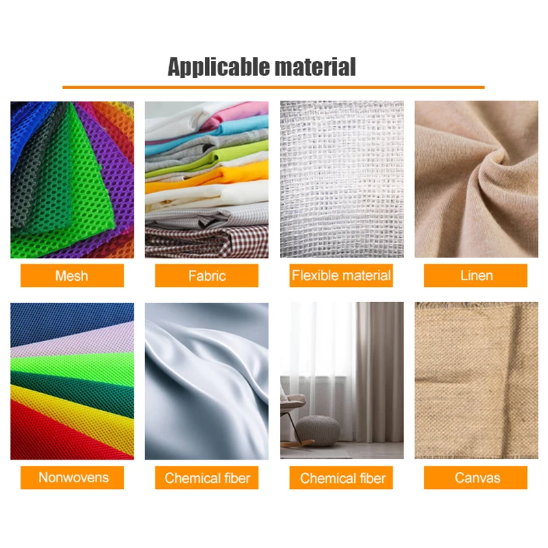
| Garment and footwear fabric cutting | Multi-layer woven, stretch jersey and technical textiles |
| Automotive interior trimming | Leather, sponge composite leather, foam laminates |
| Gasket and seal production | Rubber, silicone, PVC and soft glass sheets |
| Flexible packaging sample making | Corrugated board, grey board and folding carton stock |
| Composite panel processing | Foam core, honeycomb and multi-layer bonded materials |
Why the Wrong Tool Head Costs More Than the Machine
A blade specified for standard woven will tear stretch jersey and crush open-cell foam, silently destroying yield long before anyone notices.
When buyers evaluate a CNC oscillating knife cutting machine specifications sheet, the conversation almost always starts with working area and ends with price. What gets skipped is the match between tool head geometry and the actual material on the table. I once stood in a Dubai garment workshop watching a stretch zebra-pattern jersey slip across a conveyor because the vacuum zone layout was designed for rigid board, not limp knit. The cutter ran, but the sewing line downstream starved for accurate panels [NEED_CITE: vacuum zoning requirements for flexible textile versus rigid board]. Selecting the correct oscillating frequency, blade angle and hold-down pressure for each fabric type prevents ragged edges, delaminated composites and crushed foam cores that only show up after the nesting software has already counted the piece as cut.
Oscillating Knife Mechanics on Fabric and Foam
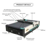
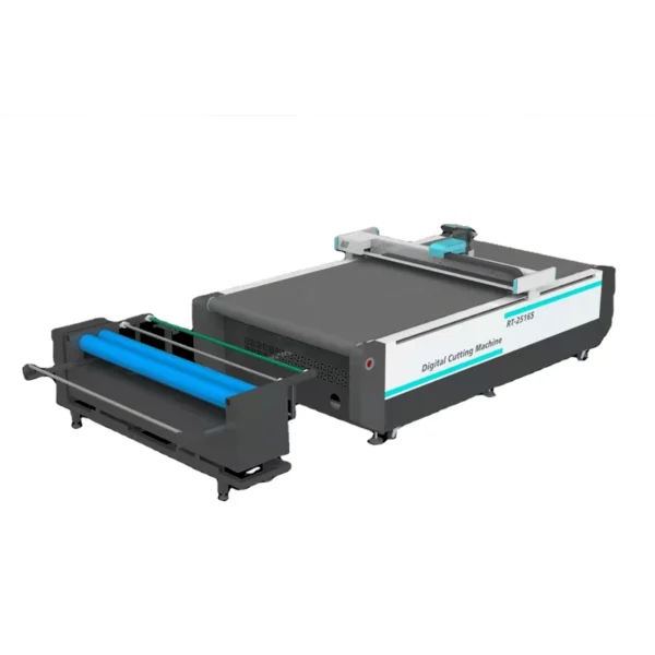
The Swiss imported oscillating knife head on this flatbed digital cutting system delivers full cutting, half cutting and cursor location in a single tool station. High-frequency vibration lets the blade slice through multi-layer fabric stacks without dragging the bottom ply, a problem that shows up as skewed pattern pieces once the stack is separated. For sponge composite leather used in automotive interiors, the same head adjusts stroke length to kiss-cut the top layer while leaving the backing intact, a requirement that drag knife tooling simply cannot meet without crushing the foam cell structure.
Vacuum Hold-Down and Conveyor Tension Control
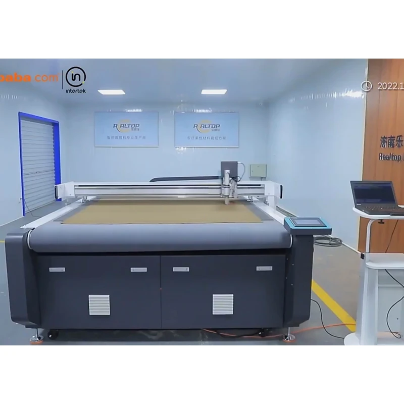
The 7.5 kW vacuum pump feeds through a high-density felt conveyor belt imported from Germany, creating the friction and suction balance needed to keep limp textiles flat during 800–1200 mm/s travel speeds. On open-weave mesh or slippery stretch jersey, the auto feeder and hold-down roller work together to maintain sheet tension before the material reaches the cutting zone. Without this coordination, the vacuum table alone cannot prevent edge lift on small pattern pieces, and the oscillating knife catches the lifted edge, producing a miscut that the nesting software has already counted as finished [NEED_CITE: material lift incidents on conveyor-based cutting systems].
Reading the Specifications That Actually Matter
The Taiwan Hiwin linear rail paired with a ball screw drive delivers ≤ 0.1 mm repeated accuracy across the full 1600 × 2500 mm working area, a tolerance that matters when garment pattern pieces must align with printed grain lines. Translational velocity of 800–1200 mm/s is achievable on standard woven; thicker sponge composites require the servo motor to reduce travel speed so the oscillating blade completes each stroke before the carriage advances. The HP-GL compatible instruction system accepts DXF and PLT files from common nesting software, but file format and nesting workflow compatibility must be confirmed on the buyer’s actual production files before the order is placed, not after the machine arrives on the factory floor.
The Hidden Cost of Skipping the Sample Cut
Quoting a cutting machine on working area alone leads to two failures that surface only during production. First, the material thickness exceeds the effective cutting depth of the chosen blade, leaving uncut fibers at the bottom of a multi-layer stack that operators must finish by hand. Second, the vacuum zone layout holds rigid board perfectly but allows small leather pieces to shift during the final pass, turning a nested sheet into scrap. Both problems trace back to a configuration that was never tested against the buyer’s actual material [NEED_CITE: post-delivery reconfiguration costs on digital cutting equipment]. Requesting a sample cutting report on your own fabric, leather or composite stock before commitment eliminates both risks.
Why Source This Configuration Here
The design and production of both knife and laser cutting systems under one roof means the cutting method is matched to the material rather than forced into whichever technology a single-technology vendor happens to offer. Tool head and table zoning configurations are specified per material type and daily volume, not sold as a one-size package. CCD camera positioning for printed contour work is available for garment and signage applications where pattern alignment depends on tracking registration marks at production speed. Software file format compatibility is confirmed on the buyer’s existing nesting workflow before the order is placed. Voltage, plug type and control language are documented and locked in the electrical schematic before the machine enters assembly, preventing the on-site mismatch that delays commissioning.
Documentation & Verification
- Machine specification sheet listing tool head and vacuum table zoning per material
- Electrical schematic confirming 380 V ± 10 % supply and plug type for destination
- Sample cutting report run on buyer’s own fabric or composite material
- Factory test record documenting repeated accuracy across full working area
- Software licence with confirmed DXF/PLT file format and nesting workflow compatibility
- Spare parts list identifying oscillating knife blades, felt belt sections and vacuum seals
Installation, Commissioning & Support
- Foundation must support 3450 × 2300 mm footprint with level tolerance for linear rail alignment
- Dedicated 380 V ± 10 % circuit required for combined 9 kW machine and 7.5 kW vacuum pump load
- Machine ships as a single assembly; conveyor belt tension and vacuum zone seals are verified on site
- First-run calibration includes oscillating knife stroke tuning on the buyer’s specific material thickness
- Operator training covers HP-GL file import, nesting workflow and tool head changeover procedures
- Preventive maintenance schedule covers felt belt inspection, Hiwin rail lubrication and vacuum filter replacement
Before You Send the Inquiry
Provide the exact material type, thickness range and maximum sheet size you plan to process, along with the daily volume target and whether your workflow relies on printed registration marks for contour cutting. Confirm your facility voltage and frequency, preferred control language, and any existing nesting software whose file format must be imported without conversion. If your material is a stretch knit, open-weave mesh or multi-layer composite, request a sample cut on your own stock before finalizing the tool head and vacuum table configuration.
Frequently Asked Questions
Q: How do I choose between oscillating knife and drag knife for my material?
A: Oscillating knife suits multi-layer fabric, foam and sponge composite where the blade must slice without dragging the bottom ply. Drag knife works on thinner vinyl, gasket and single-ply leather where a pulling cut is acceptable. The correct choice depends on material thickness, layer count and edge quality requirement, all confirmed during sample cutting before the order is placed.
Q: Can the CCD camera track printed marks on stretch fabric at full speed?
A: CCD contour recognition is available as a configuration option for printed pattern alignment. Tracking reliability depends on mark contrast, fabric stability under the hold-down roller and the translational velocity set for that specific material. We verify tracking accuracy on your printed fabric during the sample cutting stage, not after delivery.
Q: Will the vacuum table hold small pattern pieces without lifting?
A: Vacuum zoning divides the table into sections that can be activated independently to match the nested sheet layout. Small pieces on open-weave or slippery stretch material require sufficient zone density and felt belt friction. The 7.5 kW pump and high-density felt conveyor address this, but the exact zone configuration must be matched to your typical nesting pattern before build.
Q: Does the software accept my existing DXF and PLT nesting files?
A: The HP-GL compatible instruction system imports standard DXF and PLT formats. Compatibility with your specific nesting software output, including layer naming, cut order and tool path assignment, must be confirmed on your actual production files before the order is finalized to avoid post-delivery conversion work.
Q: How are voltage, plug and language confirmed before shipment?
A: An electrical schematic and voltage confirmation document are issued before production begins, locking in the 380 V ± 10 % supply requirement, destination plug type and control interface language. This document is signed off by the buyer so the machine arrives with the correct electrical and software configuration, eliminating on-site rewiring or language pack delays.


商品评价
Clear filtersThere are no reviews yet.