


Fast Shipping
Carrier information

20k products
Payment methods

24/7 Support
Unlimited help desk

2-day Delivery
Track or off orders
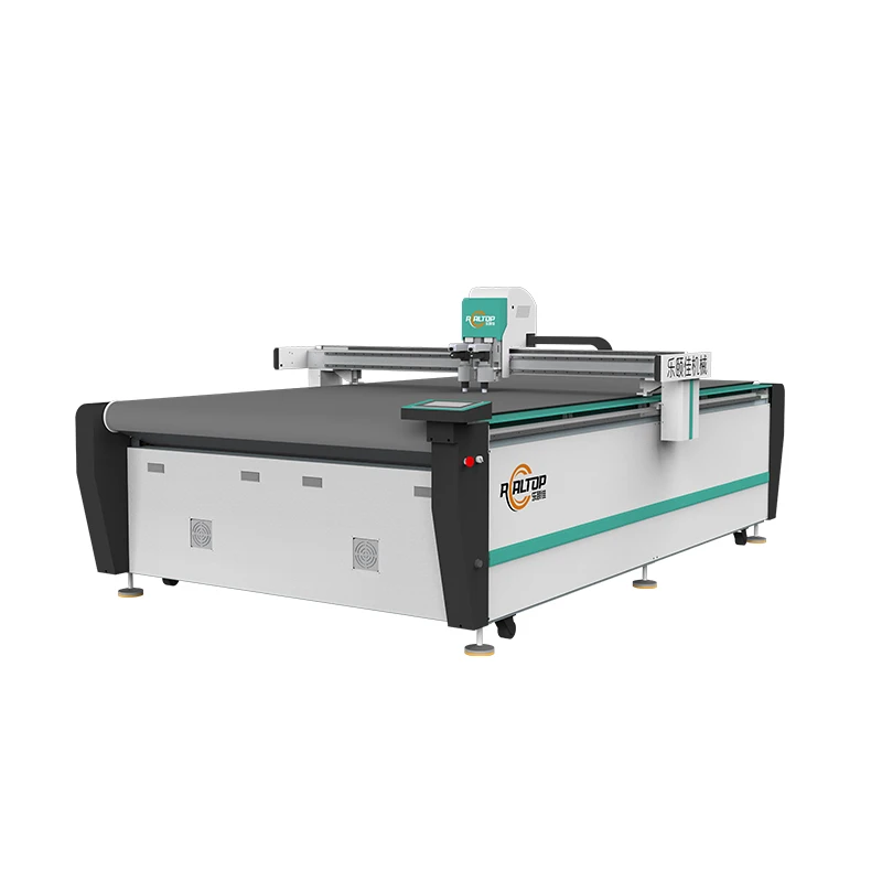
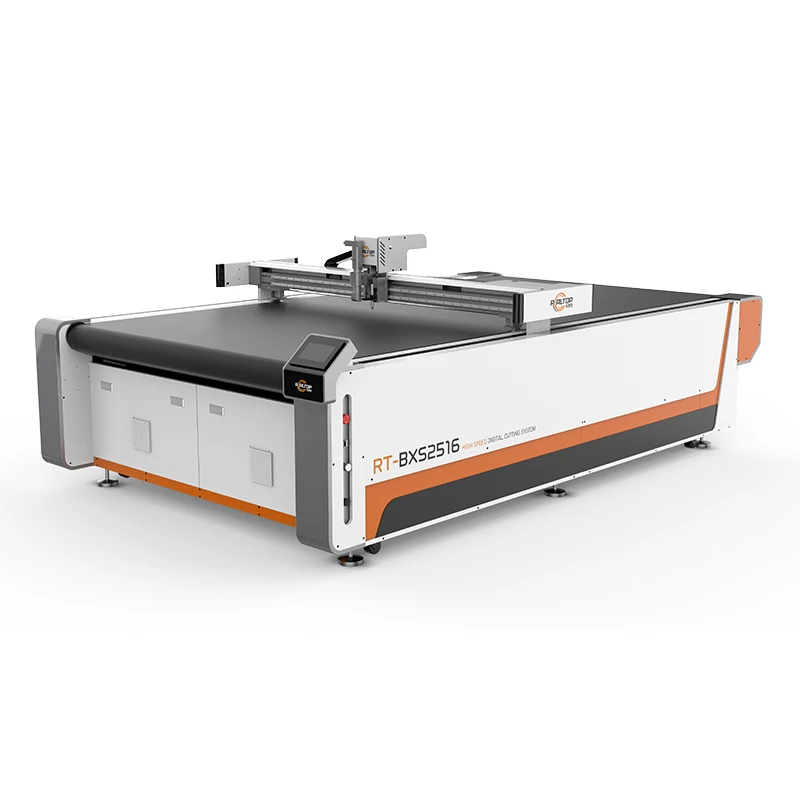
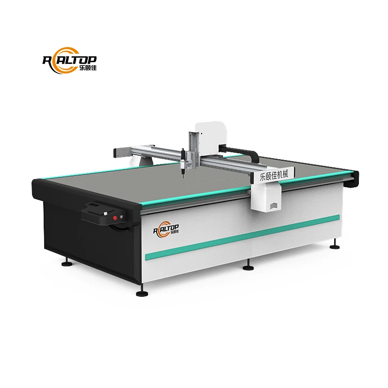
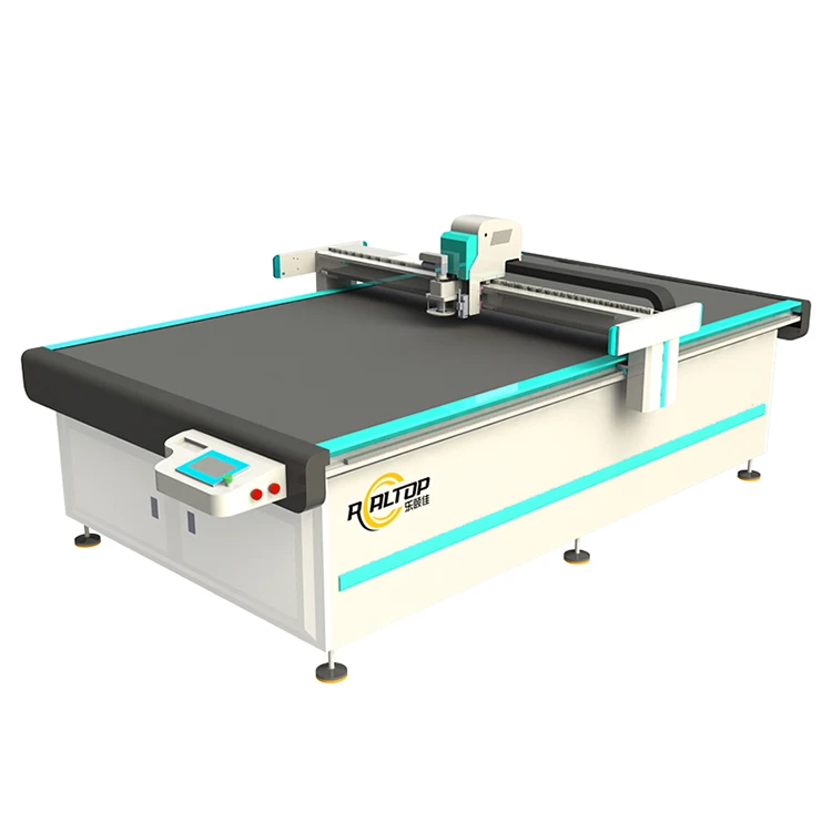
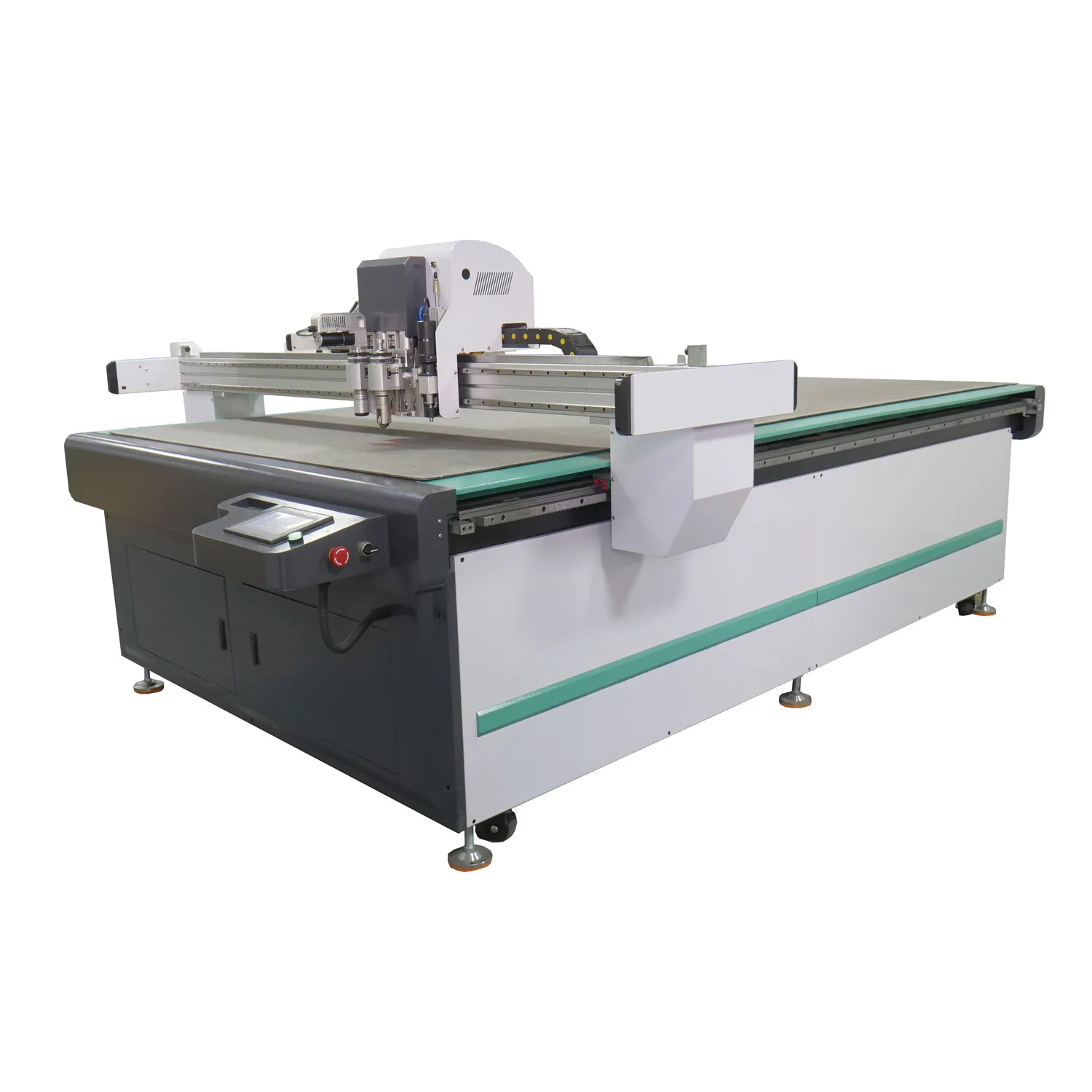
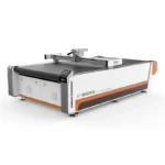
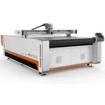
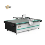
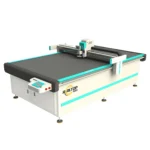
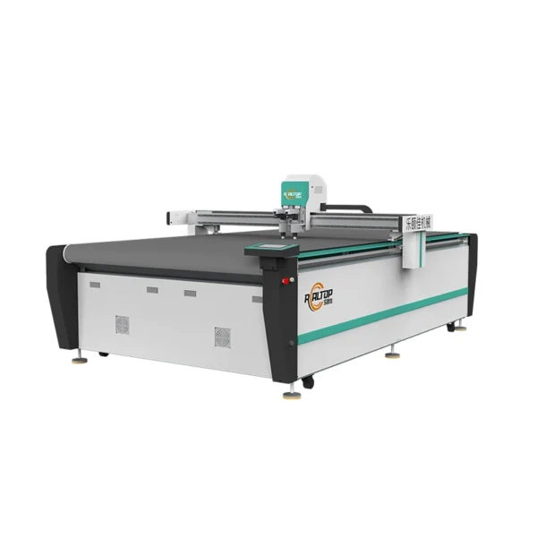
Configurable Tooling Approach — The RT-D2516/RT-S2516 allows composite fabricators to match oscillating knife, drag knife, or specialty tool heads to their specific material density and cutting depth requirement before production begins.
Technical Specifications
| Parameter | Value |
|---|---|
| Model | RT-D2516 / RT-S2516 |
| Product Type | CNC Oscillating Knife Cutting Machine for Composites |
| Working Area | 1600 × 2500 mm |
| Overall Dimensions (L×W×H) | 3450 × 2300 × 1250 mm |
| Rated Power | 9 kW |
| Voltage | 380V ±10% |
| Vacuum Pump | 7.5 kW (aviation aluminum shell, built-in silencer sponge) |
| Table Surface | Magnesium-aluminum alloy with PVDF fluorocarbon coating, anodic and hard oxidation treatment |
| Translational Velocity | 800–2000 mm/s |
| Cutting Speed | 200–800 mm/s (basis to be confirmed per material type and thickness) |
| Cutting Thickness | Up to 100 mm (varies with material) |
| Repeated Accuracy | ≤0.1 mm |
| Transmission System | Digital servo motor (Delta; Panasonic optional), Taiwan Hiwin linear guide, synchronous belt, ball screw |
| Tool Head Options | Swiss imported oscillating knife (vibration full cutting, half cutting, cursor location); optional pneumatic knife, high-power vibrating knife, circular knife, V-cutting knife, drag knife, creasing wheel, dotted line knife, punching, brush |
| Visual Positioning | Small CCD mark point positioning, panoramic camera recognition, projection positioning (optional) |
| Conveyor | German imported conveyor belt (auto-feeding) |
| Safety Devices | Infrared induction blocking, dual-side beam anti-collision sensors, emergency stop with in-situ resume |
| Control Format | HP-GL compatible |
| Standard | CE (certificate number not stated in source) |
| Warranty | One year (domestic and abroad) |
Application Suitability
| Application | Material or Output |
|---|---|
| Automotive interior structural panels | Carbon fiber sheets, glass fiber reinforced composites, multilayer prepreg layups |
| Gasket and seal production | Sponge composite leather, PVC, silicone rubber, soft glass |
| Footwear and bag component cutting | Flexible composite fabrics, foam-backed textiles, synthetic leather layers |
| Signage and display fabrication | Rigid composite boards, lightweight honeycomb panels, PVC foam board |
| Home furnishing composite panels | Decorative laminate sheets, acoustic insulation composites, soft foam layers |
Why Ragged Edges on Composites Usually Trace Back to the Tool Head, Not the Machine
Selecting the oscillating knife profile after testing on the buyer’s exact material prevents delamination and crushed fiber layers at the cut edge.
I once flew across the country because a client’s carbon fiber prepreg was delaminating on every pass. The sample we cut in our workshop came out clean, but their production roll had a different resin content. The vibration frequency and blade angle that worked on our sample simply pushed the layers apart on theirs. That experience changed how I approach every composite cutting inquiry now — the material in your facility is the only material that matters. A CNC oscillating knife cutting machine for composites specifications sheet only tells half the story until the blade meets your actual workpiece [NEED_CITE: common causes of delamination in composite cutting operations].
Tool Head Selection That Follows the Material, Not the Other Way Around
The Swiss imported oscillating knife on the RT-D2516/RT-S2516 supports vibration full-cutting, half-cutting, and cursor location modes, each producing a different interaction with composite fiber layers. For carbon fiber panels where edge integrity matters for structural performance, full-cutting at the correct oscillation frequency separates fibers cleanly. For softer sponge composites used in automotive interiors, half-cutting scores the top layer without penetrating the backing. The optional high-power vibrating knife and pneumatic knife address denser layups where standard oscillation stalls mid-pass. Matching the tool head to the composite density and resin content is the decision that determines whether the CNC oscillating knife cutting machine for composites specifications translate into usable parts or scrap.
Vacuum Table Engineering for Flat Composite Sheets
Composite panels warp if suction is uneven across a 1600 × 2500 mm surface, and warped panels produce dimensional errors that compound through downstream assembly. The magnesium-aluminum alloy table with PVDF fluorocarbon coating resists resin adhesion and chemical exposure common in prepreg and wet-layup environments. The 7.5 kW vacuum pump with aviation aluminum housing and integrated silencer sponge maintains consistent suction without adding noise to the cutting area [NEED_CITE: vacuum adsorption requirements for flatbed CNC cutting of composite panels]. Zoning on this table addresses the problem of small composite parts lifting at the edges during high-speed passes, which is where most vacuum-related cutting failures originate.
Reading the Specifications Against Real Production Conditions
The ≤0.1 mm repeated accuracy depends on the Delta or Panasonic servo motors driving the Taiwan Hiwin linear guides — this combination controls positional drift during long cutting runs on large composite sheets. Translational velocity reaches 2000 mm/s, but cutting speed ranges from 200 to 800 mm/s depending on composite type and thickness; a 3 mm carbon fiber sheet and a 20 mm PVC foam panel demand different feed rates to maintain edge quality. The HP-GL compatible control format determines which nesting software files the machine accepts directly, and confirming file compatibility before order prevents workflow interruptions. The CCD camera options — mark point, panoramic, or projection — each serve different contour-cutting workflows, from printed registration marks on decorative composites to projection-guided alignment on irregular layup shapes.
What Happens When Vacuum Zoning Is Wrong for Your Part Size
Small composite gaskets and intricate automotive trim pieces lift off the table during high-speed knife passes if the vacuum zones are not sized for them. Once a part shifts even slightly, the CCD camera loses its registration mark and the remaining cuts in that nest become scrap. I have seen production lines discard entire sheets of carbon fiber prepreg because the vacuum could not hold the perimeter of a narrow component during the final contour pass [NEED_CITE: effects of vacuum zoning on small-part retention during CNC knife cutting]. The consequence is not just wasted material — it is the downtime spent re-nesting the job and the delay to downstream assembly schedules.
Why Sourcing This Machine Here Makes Sense for Composite Fabricators
In-house design covers both oscillating knife and drag knife cutting technologies, meaning a composite fabricator can specify the cutting method matched to their material rather than adapt to a single tooling philosophy. The tool head and table configuration is confirmed per material type, thickness, and production volume before the order enters the build queue. CCD camera positioning type is selected alongside the software file format to match the buyer’s existing nesting workflow. Voltage, plug type, and control language are verified against the destination market before shipment — not discovered on arrival. Sample cutting on the buyer’s actual composite material runs before commitment, generating a report that documents edge quality, cutting depth, and achievable speed at the buyer’s specified thickness.
Documentation & Verification
- Sample cutting report on your composite material documenting edge quality, depth, and speed
- Electrical schematic with 380V ±10% confirmation and plug type for your market
- Tool head and table configuration list matched to your material and daily volume
- Machine specification sheet covering all configured knife heads and CCD camera type
- Software license and file format compatibility note for your nesting workflow
- Factory test record showing repeated accuracy and cutting performance before dispatch
Installation, Commissioning & Support
- Requires a dedicated 380V ±10% circuit rated for the 9 kW total system draw including the 7.5 kW vacuum pump
- Flat working table measures 3450 × 2300 × 1250 mm overall, with clearance needed for conveyor belt auto-feeding
- Machine ships fully assembled with calibrated Hiwin linear guides and pre-tensioned synchronous belts
- First-run parameter setting covers oscillation frequency, knife depth, and vacuum zone mapping for your material
- Operator training includes tool head changeover procedures and CCD camera calibration for contour work
- Spare parts list covers Swiss knife blades, conveyor belt segments, and vacuum pump silencer sponge replacements
What to Share Before Requesting a Quotation
To recommend the correct tool head and vacuum configuration, we need your composite material type, resin content if applicable, sheet dimensions, and maximum cutting thickness. Your daily part volume and nesting layout determine whether auto-feeding conveyor integration and specific CCD camera positioning will support your throughput. Share your current nesting software and file format so compatibility is confirmed before the machine enters production.
Frequently Asked Questions
Q: How do I choose the right oscillating knife tool head for my composite material thickness and density?
A: Tool head selection starts with your material’s resin content, fiber orientation, and total thickness. The Swiss imported knife offers full-cutting and half-cutting modes — full-cutting suits structural carbon fiber panels requiring clean through-cuts, while half-cutting scores softer sponge composites without penetrating the backing. We run your actual material on sample machines to confirm which mode and blade profile produces the edge quality your downstream process requires.
Q: Which CCD camera positioning option works for my printed contour cutting workflow?
A: Small CCD mark point positioning suits jobs with consistent printed registration marks at known intervals. Panoramic camera recognition handles large-format nested layouts where marks appear across the full 1600 × 2500 mm working area. Projection positioning assists operators placing irregular composite layups manually. We confirm which option matches your printing method and nesting software before order.
Q: Is the vacuum table zoning adequate for small composite parts, and how is suction maintained?
A: The magnesium-aluminum alloy table with PVDF coating provides uniform adsorption across the full working area, and zoning prevents small gaskets and trim pieces from lifting at the edges during high-speed passes. The 7.5 kW pump maintains suction pressure even when multiple zones are active. We verify zone performance against your smallest part dimensions during the sample cutting phase.
Q: How do we confirm voltage, plug type, and control language before shipment?
A: We document your facility’s supply specification — 380V ±10% with the required frequency and plug standard — on the electrical schematic before production begins. Control interface language is confirmed alongside the software file format compatibility note. All three items appear on the pre-shipment specification confirmation so there are no surprises when the machine arrives on your floor.
Q: Can you run a sample cut on my specific composite material before I place the order?
A: Yes. Send your production material and we run it on the configured tool head and table setup intended for your order. The sample cutting report documents edge quality, achievable cutting speed at your thickness, delamination check results, and vacuum hold-down performance on your part geometry. You review this report before making a commitment.


商品评价
Clear filtersThere are no reviews yet.