



Fast Shipping
Carrier information

20k products
Payment methods

24/7 Support
Unlimited help desk

2-day Delivery
Track or off orders
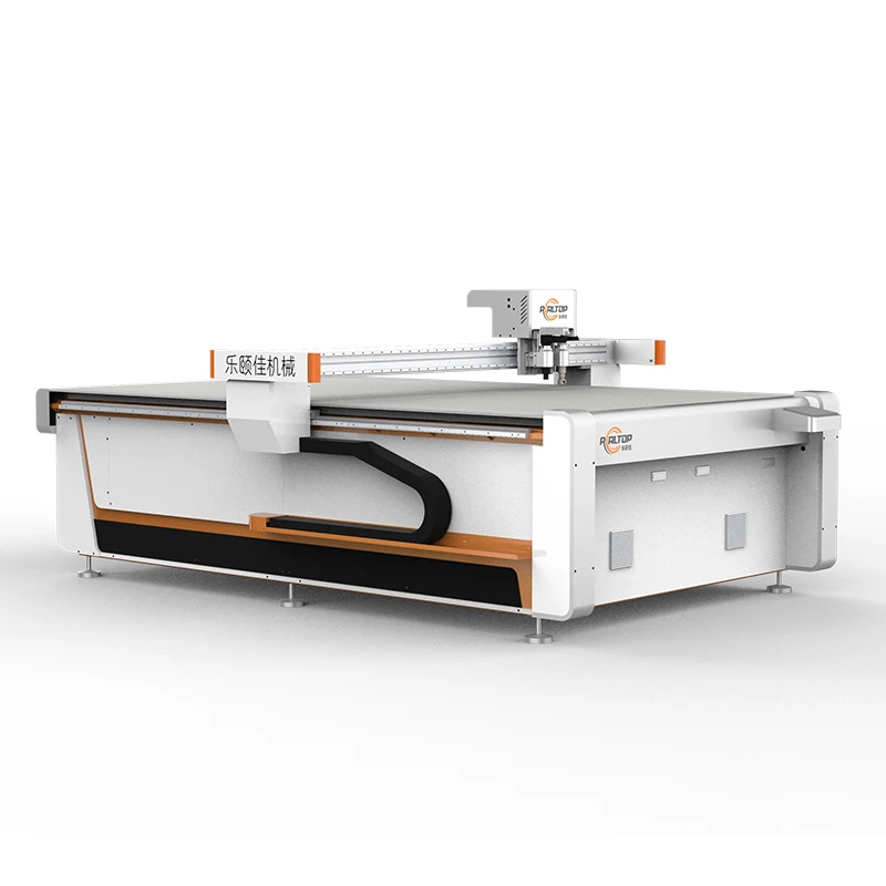
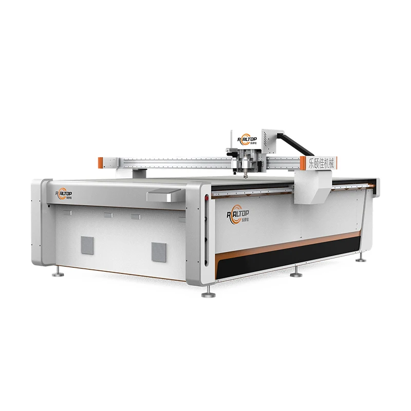
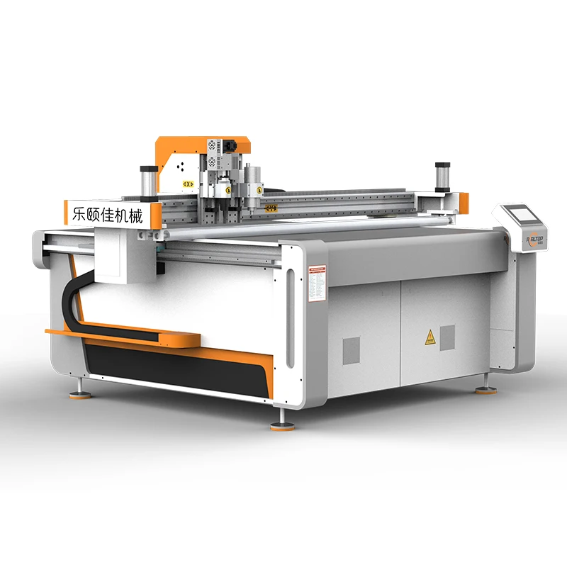
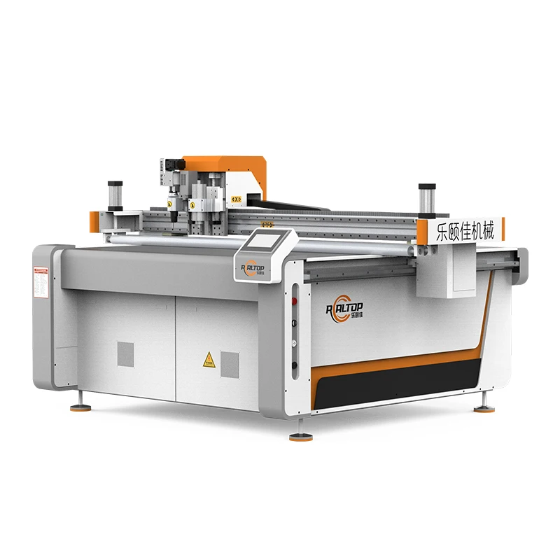
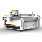
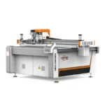
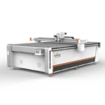
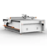
Material-Specific Tooling — Each RT-D2516/RT-S2516 unit leaves the factory with tool heads and vacuum zoning specified against the buyer’s own sample stock, not a generic defaults sheet.
Technical Specifications
| Parameter | Value |
|---|---|
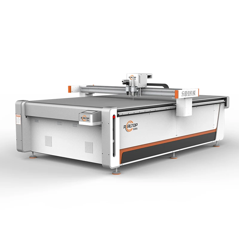
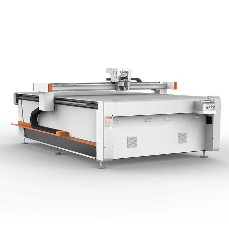
| Product Type | CNC Oscillating Knife Cutting Machine |
| Model | RT-D2516/RT-S2516 |
| Working Area | 1600 × 2500 mm |
| Overall Dimensions | 3450 × 2300 × 1250 mm |
| Rated Power | 9 kW |
| Voltage | 380V ±10% |
| Table Type | Flat working table or auto-feeding table (conveyor belt, Germany imported) |
| Tool Head Options | Swiss imported knife, oscillating knife, pneumatic knife, high-power vibrating knife, circular knife, V-cutting knife, drag knife, creasing wheel, dotted line knife, punching, brush |
| Translational Velocity | 800–2000 mm/s |
| Cutting Speed | 200–800 mm/s (according to different cutting materials) |
| Cutting Thickness | ≤100 mm (varies with material; basis to be confirmed) |
| Repeated Accuracy | ≤0.1 mm |
| Transmission System | Digital servo motor (Delta or Panasonic optional), Taiwan Hiwin linear guide, synchronous belt, ball screw |
| Instruction System | HP-GL compatible format |
| Vacuum Pump | 7.5 kW, integrated aviation aluminum shell with built-in silencer sponge |
| Vacuum Table | Magnesium-aluminum alloy, fluorocarbon PVDF powder spraying, anodic oxidation, hard oxidation |
| Safety Device | Infrared sensors, anti-collision, emergency stop |
| Control Panel | Touch screen, multiple languages supported |
| Software Compatibility | Auto typesetting; supports PLT, DXF, AI formats |
| Language Options | English, Russian, Italian, Chinese, and others (customizable) |
| Assembly State | Fully assembled |
| Standards | CE |
Application Suitability
| Application | Material or Output |
|---|---|
| Carton and packaging sample making | Corrugated cardboard, honeycomb cardboard, plastic box stock |
| Signage and graphic production | Sticker, film, PVC, PP, PE foam board |
| Automotive interior fabrication | PU, EVA, XPE, composite materials, sponge |
| Gasket and sealing pad cutting | PTFE, ETFE, rubber, fiberglass |
| Garment and footwear production | Leather, fabric, textile, non-woven fabric, shoe material, luggage material |
| Composite and foam fabrication | Foam board, PU, EVA, XPE, composite layered materials |
What the Wrong Tool Head Costs You Before the First Shift
Matching blade type, stroke frequency, and vacuum zoning to the actual material prevents the edge crush and delamination that force rework on day one.
When a packaging house specifies a CNC oscillating knife cutting machine based purely on bed size, the first run on honeycomb cardboard often reveals that the standard oscillating blade tears the flute structure rather than shearing it cleanly. The creasing wheel may score too shallow or too deep for the board grade in use. These mismatches surface after the machine is installed, when returning it is no longer practical [NEED_CITE: common tool head mismatches in packaging digital cutting].
I have walked through workshops in Chile where the operator had dialed the oscillation frequency to maximum trying to get through a dense honeycomb core, only to produce a fuzzy edge that failed the customer’s glue-line test. The machine was not at fault — the tool head selection was. That is why every configuration must be locked against a physical sample before production begins.
Tool Head Selection Drives Edge Quality More Than Motor Power
The RT-D2516/RT-S2516 platform supports a wide range of heads — oscillating knife, drag knife, creasing wheel, V-cutting knife, pneumatic knife, and punching — because no single blade geometry cuts corrugated board, leather, and foam with the same edge quality. An oscillating knife handles thick foam and honeycomb by vibrating through the material in a reciprocating motion, while a drag knife suits thinner vinyl and sticker films where a continuous draw produces the cleanest contour. Specifying the correct head for each primary material avoids the ragged edges and crushed cores that slow down downstream assembly.
Vacuum Zoning and Table Flatness for Small Parts and Thin Films
The magnesium-aluminum alloy table with PVDF coating and hard oxidation provides a flat surface that maintains uniform suction across zones. Small packaging inserts and narrow gasket strips tend to lift at the edges when vacuum distribution is uneven, causing the blade to catch and tear the stock. Zoned vacuum control — combined with the 7.5 kW pump — holds these parts in place without requiring mechanical clamps that would interfere with the cutting path. This is particularly relevant when cutting nested layouts where offcuts between parts are narrow and prone to shifting.
How Servo Specification and Drive Components Shape Repeated Accuracy
The repeated accuracy of ≤0.1 mm depends on the interaction between the Delta or Panasonic servo motors, Taiwan Hiwin linear guides, and synchronous belt transmission. Servo motors with vibration suppression maintain positional accuracy during the rapid directional changes that contour cutting demands [NEED_CITE: servo motor tuning and positional drift in CNC cutting tables]. When the cutting path includes tight radii on corrugated carton samples or intricate gasket profiles, any lag in the drive system translates directly into deviation from the DXF or PLT file geometry. The IP67 waterproof rating on the servos also matters in environments where coolant mist or adhesive overspray is present.
The Hidden Cost of Skipping Material-Specific Configuration
Buyers who confirm only the working area and skip the material trial frequently encounter problems that do not show up on the specification sheet. A vacuum table with insufficient zoning leaves small carton blanks lifting during the cut. A CCD system promised for printed contour work may not track registration marks at full production speed if the camera resolution and processing algorithm are not matched to the print quality in use [NEED_CITE: CCD positioning accuracy under varying print contrast conditions]. Software that cannot import the buyer’s nesting files forces manual re-drawing, adding time to every job. These issues compound because each one is discovered only after the machine arrives and the first real production run begins.
Why Sourcing This Platform Directly From the Factory Matters
In-house design covering both knife and laser cutting technologies means the recommendation for a given material comes from engineers who build both systems, not from a catalog that only lists one. The tool head and table configuration for the RT-D2516/RT-S2516 is specified per material and production volume before the order is placed, not selected from a default package. CCD camera positioning — available as small mark-point, panoramic, or projection positioning — is confirmed against the buyer’s actual printed stock. Voltage, plug type, and control panel language are documented and locked before shipment, eliminating the on-site rewiring and reprogramming that delay commissioning. Sample cutting on the buyer’s own material is completed and reported before the buyer commits to the purchase order.
Documentation & Verification
- Machine specification sheet listing confirmed tool heads and table zones for your material
- Electrical schematic with voltage and frequency matched to your facility supply
- Sample cutting report on your corrugated or honeycomb stock with edge photos
- Tool head and table configuration list signed off before production starts
- Software licence and file format compatibility note for PLT, DXF, and AI files
- Packing photographs showing vacuum table surface and tool head assembly before crating
Installation, Commissioning & Support
- Requires a level floor supporting the 3450 × 2300 × 1250 mm footprint and 9 kW power draw
- Dedicated 380V ±10% circuit with correct plug type confirmed before dispatch
- Ships fully assembled; positioning and leveling on site without major reassembly
- First-run calibration of servo drives, vacuum zones, and tool head stroke on your material
- Touch-screen control training in confirmed language covering file import and nesting workflow
- Spare parts list covering blades, vacuum seals, and conveyor belt segments
- Scheduled maintenance intervals for Hiwin linear guides and synchronous belt tension checks
What We Need to Configure Your Machine Correctly
To match the RT-D2516/RT-S2516 to your production environment, send the material type, maximum thickness, and sheet dimensions you will run most frequently. Specify your local voltage, frequency, and plug standard so the electrical system is built to match. Let us know which file formats your design team currently uses and whether printed contour recognition is part of your workflow, so the correct CCD option and software compatibility can be confirmed before the order is finalized.
Frequently Asked Questions
Q: How do I choose between an oscillating knife and a drag knife for my material?
A: Oscillating knives suit thicker, denser materials like honeycomb cardboard, foam, and gasket stock where a reciprocating blade motion shears through the full depth cleanly. Drag knives work best on thinner, flexible materials like vinyl, sticker film, and fabric where a continuous drawn cut follows contours without fraying. The selection depends on your primary material thickness and edge quality requirement, and we confirm this with a sample cut on your actual stock before the order is placed.
Q: Which CCD positioning method fits printed contour cutting?
A: The platform offers small CCD mark-point positioning, panoramic camera recognition, and projection positioning. Small CCD works when your print includes clearly defined registration marks. Panoramic recognition suits jobs with varying mark placement across large sheets. Projection positioning overlays the cut path onto the material for visual alignment before cutting. We test your printed sample to determine which method tracks reliably at your intended cutting speed [NEED_CITE: CCD positioning method selection criteria for digital cutting tables].
Q: How does vacuum table zoning affect small part cutting?
A: When cutting narrow carton inserts or small gasket profiles, the offcuts between parts leave limited surface area for vacuum hold-down. Zoned vacuum control directs suction only to the active cutting area, preventing small parts from lifting as the blade exits the cut. The magnesium-aluminum table with PVDF coating provides a flat surface that maintains consistent contact with the material across all zones.
Q: What electrical and language details are confirmed before shipment?
A: Voltage, frequency, plug type, and control panel language are documented and locked before the machine enters production. The 380V ±10% system is configured to your facility supply, and the touch-screen interface is set to your preferred language from the supported options. This prevents on-site electrical rework and operator confusion during commissioning.
Q: Can I see cutting results on my own material before committing?
A: Yes. We require a sample of your actual material — the specific board grade, foam density, or composite layup you will run in production. The sample cutting report documents edge quality, achieved cutting depth, and cycle time under the tool head configuration recommended for your application. You review and approve this report before the purchase order is finalized.


商品评价
Clear filtersThere are no reviews yet.