

Fast Shipping
Carrier information

20k products
Payment methods

24/7 Support
Unlimited help desk

2-day Delivery
Track or off orders
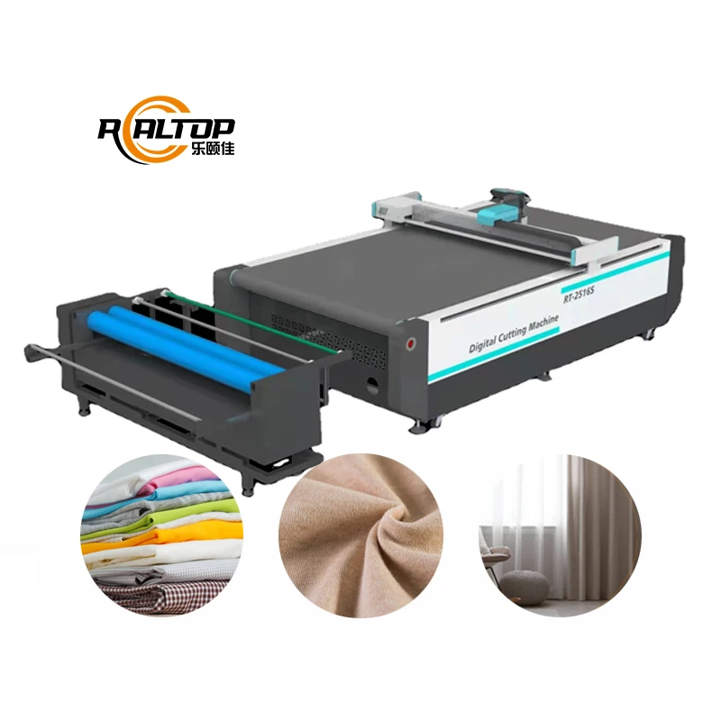
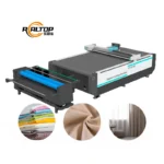
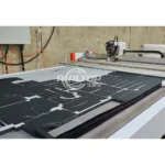
Modular Tooling Configuration — The RT-D2516/RT-S2516 supports multiple cutting modes including Swiss vibration full cut, half cut, and cursor location on a single tool head, eliminating forced compromises between fabric edge quality and throughput speed.
Technical Specifications
| Parameter | Value |
|---|---|
| Model | RT-D2516/RT-S2516 |
| Product Type | CNC Oscillating Knife Cutting Machine |
| Working Area | 1600 × 2500 mm |
| Overall Dimensions | 3450 × 2300 × 1250 mm |
| Rated Power | 9 kW |
| Cutting Thickness | ≤50 mm (varies by material density and layer count) |
| Translational Velocity | 800–1200 mm/s |
| Repeatability | ≤0.1 mm |
| Tool Head | Swiss imported knife with vibration full cut, vibration half cut, and cursor location |
| Transmission System | Digital servo motor, linear guide, synchronous belt, ball screw |
| Servo Motor | Panasonic |
| Vacuum Pump | 7.5 kW |
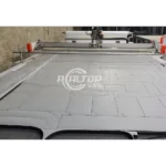
| Table Surface | High-density felt on aviation aluminum top with inner wind structure |
| Machine Bed | Overall welding process, imported milling machine processing |
| Safety Device | Infrared sensors |
| Instruction System | HP-GL compatible format |
| Voltage | 380V ± 10% |
| Other Configuration | Delta servo motor, Germany imported conveyor belt, auto feeding, Taiwan Hiwin rail |
| Certification | CE |
Application Suitability
| Application | Material or Output |
|---|---|
| Multi-layer garment fabric cutting | Woven, knitted, and non-woven textiles stacked for batch nesting |
| Automotive interior component production | Synthetic leather, sponge composite leather, and soft trim materials |
| Footwear upper and lining cutting | Natural and PU leather, flexible composite sheets |
| Gasket and seal fabrication | Rubber, silicon, PVC, and soft glass up to rated thickness |
| Printed textile contour cutting | Dyed or sublimation-printed fabric requiring CCD registration |
Why Oscillating Knife Cutting Machine Specifications Alone Cannot Guarantee Edge Quality
A machine rated for 50 mm cutting depth on foam will not deliver the same depth on dense multi-layer composite fabric without tool head reconfiguration.
Buyers often compare oscillating knife machines on working area and maximum cutting thickness, then discover that the quoted thickness was tested on a single material type under ideal conditions. When production switches to layered garment fabric or sponge composite leather, the knife oscillation frequency and stroke length may not penetrate cleanly, leaving frayed edges or incomplete cuts through bottom layers [NEED_CITE: material density variation effect on oscillating knife penetration]. The real question is not whether the machine can reach 50 mm, but whether the tool head, vacuum hold-down, and feed rate are configured together for the specific material stack you will actually run.
Tool Head Selection and Fabric Behavior
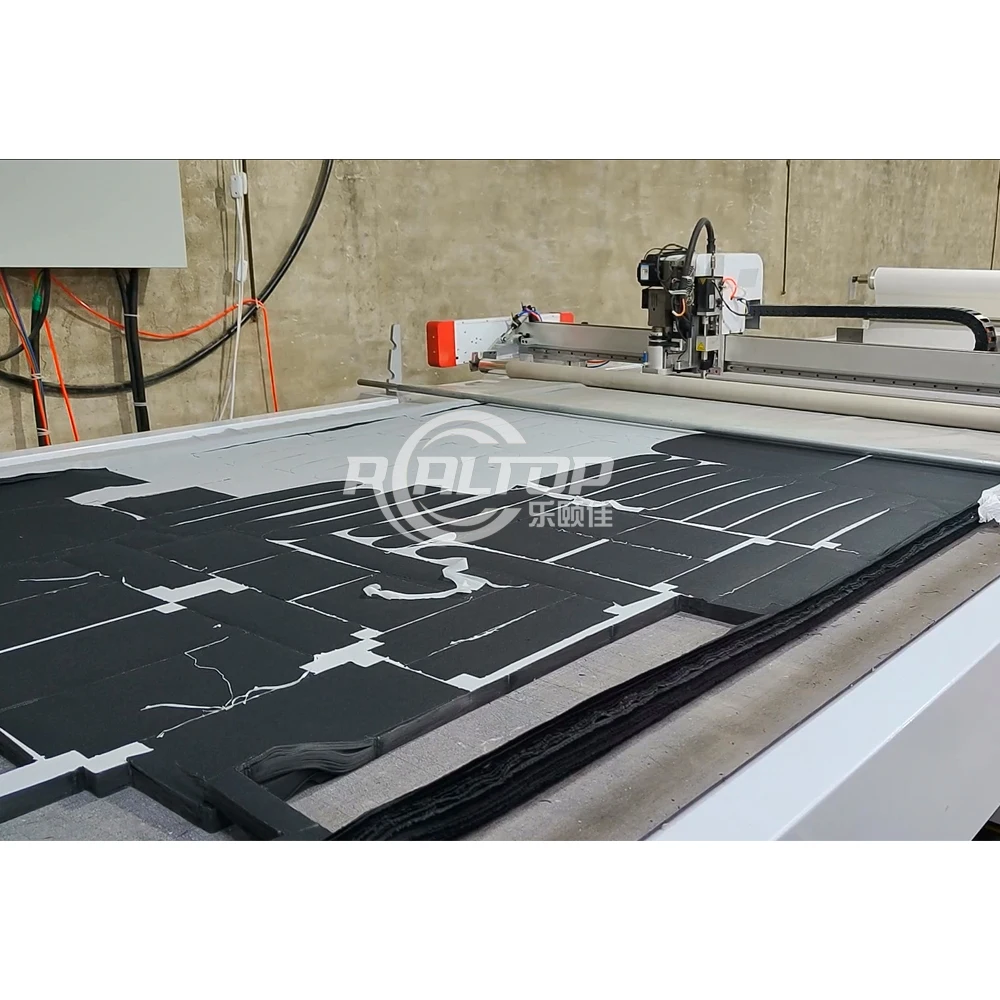
The Swiss imported knife system on the RT-D2516/RT-S2516 provides three working modes within a single head: vibration full cut for through-cutting, vibration half cut for kiss-cutting or perforation, and cursor location for precise start-point registration. This matters because different textile constructions respond differently to blade action. Tightly woven fabrics tend to fray under drag knife pressure, while loose knits can stretch and distort if the oscillation amplitude is too aggressive. Having a CNC oscillating knife cutting machine with selectable modes means the operator can match blade behavior to fabric construction without swapping heads mid-job.
Vacuum Distribution and Small Pattern Stability
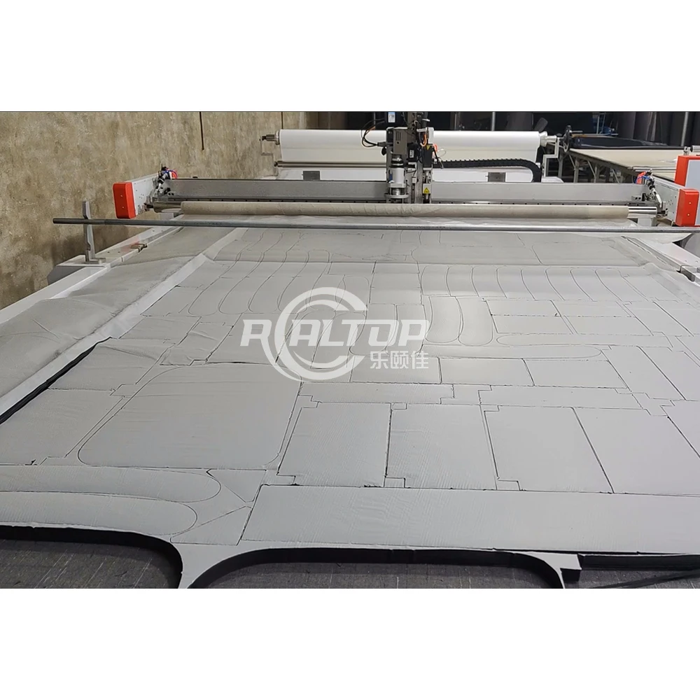
Aviation aluminum table tops with engineered internal wind channels create uniform suction across the entire 1600 × 2500 mm surface. High-density felt covers the aluminum to protect delicate fabric surfaces while maintaining vacuum transmission. When cutting small garment pattern pieces such as collars, cuffs, or pocket flaps, uneven vacuum zones allow material to lift at the edges during high-speed traversal, producing dimensional errors or knife deflection. The 7.5 kW vacuum pump paired with this table construction addresses that failure mode directly [NEED_CITE: vacuum table zoning requirements for small textile pattern cutting].
Reading the Numbers That Matter for Production
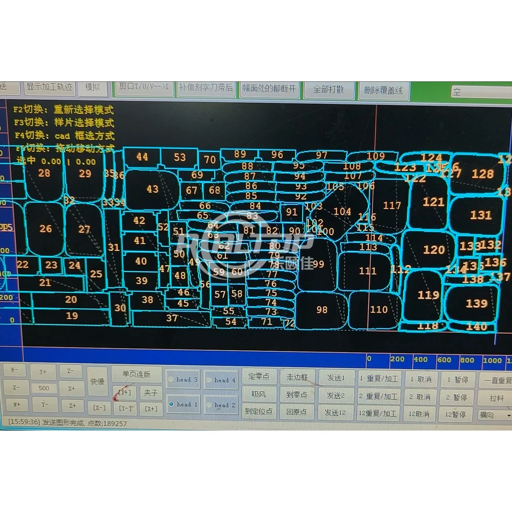
The Panasonic digital servo motors driving the linear guide and ball screw transmission deliver ≤0.1 mm repeatability, which is the tolerance band that determines whether nested pattern pieces will align correctly after cutting. The 800–1200 mm/s translational velocity range is achievable on open material, but actual cutting speed depends on material density, layer count, and contour complexity. The HP-GL compatible instruction system accepts standard vector formats, but the nesting workflow and file import chain must be validated against the buyer’s existing CAD output before the machine ships. The 9 kW rated power covers knife oscillation, servo drive, vacuum, and conveyor operation simultaneously, so electrical supply planning should account for continuous draw rather than peak-only figures.
The Cost of Skipping Material-Specific Configuration
When a buyer specifies a cutting machine on working area alone and the tool head is not matched to the material, production problems surface within the first week. Ragged edges on garment fabric require manual trimming that erodes the throughput advantage the machine was purchased to deliver. Crushed foam layers in automotive interior blanks fail dimensional inspection and must be discarded. Insufficient vacuum on small leather pieces causes lift during cutting, producing scrap instead of finished components [NEED_CITE: cost of incorrect tool head selection in textile cutting operations]. These are not warranty issues; they are configuration mismatches that could have been resolved with a sample cutting test on the buyer’s actual material before shipment.
Why Sourcing This Configuration From the Factory Floor Matters
The in-house design team covers both oscillating knife and laser cutting technologies, so material-to-method matching is decided at engineering stage rather than forced onto a single platform. Each RT-D2516/RT-S2516 leaves the factory with a tool head and table configuration list documented against the buyer’s stated material, not a generic build sheet. Sample cutting runs are performed on the buyer’s own fabric, leather, or composite before order confirmation, generating a test report that captures blade type, oscillation setting, vacuum level, and edge quality photographs. Voltage, control language, and plug type are confirmed before production begins, eliminating the mismatch that causes installation delays at the destination. The machine bed uses overall welding with imported milling machine processing, giving a stable reference surface that maintains flatness through years of vacuum cycling and knife load.
Documentation & Verification
- Machine specification sheet listing tool head mode, vacuum pump rating, and voltage confirmed for destination
- Electrical schematic with 380V ± 10% supply requirements and circuit protection details
- Sample cutting report on buyer’s fabric type, layer count, and edge quality photographs
- Tool head and table configuration list matched to stated material characteristics
- Software licence and HP-GL file format compatibility note for buyer’s nesting workflow
- Spare parts list with Swiss knife consumables and felt replacement intervals
Installation, Commissioning & Support
- Foundation must support 3450 × 2300 mm footprint with level tolerance for the aviation aluminum table
- Dedicated 380V circuit sized for 9 kW continuous draw plus startup inrush on the 7.5 kW vacuum pump
- Machine ships with conveyor belt and auto feeder pre-assembled; table leveling completed on site
- First-run calibration includes vacuum zone verification, knife stroke adjustment, and repeatability check
- Operator training covers tool head mode selection, nesting software import, and daily felt inspection
- Spare Swiss knife blades and high-density felt panels included for initial consumable coverage
What We Need to Configure Your Machine Correctly
Send us the material types you cut most frequently, including fabric composition, layer count per lay, and maximum single-sheet thickness. Specify your local voltage and frequency, the control panel language your operators require, and the CAD or nesting software currently in use so we can confirm file import compatibility. If your production includes printed textiles with contour cuts, provide sample prints so we can validate CCD registration performance before the machine enters production.
Frequently Asked Questions
Q: What cutting thickness can the oscillating knife handle across different materials?
A: The rated maximum is 50 mm, but actual cutting depth depends on material density and construction. Loose foam may cut cleanly at full depth, while densely stacked woven fabric or sponge composite leather typically requires reduced layer counts. A sample cutting test on your specific material stack determines the practical thickness limit and appropriate knife oscillation setting.
Q: Does the vacuum table hold small pattern pieces securely during high-speed cutting?
A: The aviation aluminum table top with engineered internal wind channels and 7.5 kW vacuum pump provides uniform suction across the full working area. High-density felt distributes vacuum evenly to small pieces such as collars or pocket flaps. Zone adequacy for your specific pattern size should be verified during the sample cutting phase.
Q: How does the CCD camera perform contour recognition on printed textiles?
A: CCD positioning registers printed marks for contour cutting at production speed. Performance depends on mark contrast, print consistency, and fabric surface texture. We test with your actual printed samples to confirm tracking reliability before the machine configuration is finalized for shipment.
Q: Which software file formats does the control system accept?
A: The instruction system supports HP-GL compatible formats including DXF and PLT. Compatibility with your existing nesting software and workflow should be confirmed during the pre-order stage so that file import, nesting arrangement, and cutting path generation function without manual conversion steps.


商品评价
Clear filtersThere are no reviews yet.