


Fast Shipping
Carrier information

20k products
Payment methods

24/7 Support
Unlimited help desk

2-day Delivery
Track or off orders
Precision tool head configuration per material — Every oscillating knife setup is specified against your fabric, foam or gasket stock before build, so the edge quality holds at production speed rather than degrading after the first shift.
Technical Specifications
| Parameter | Value |
|---|---|
| Model | RT-D2516/RT-S2516 |
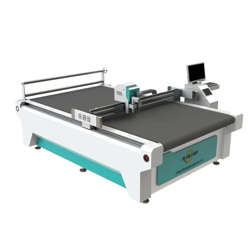
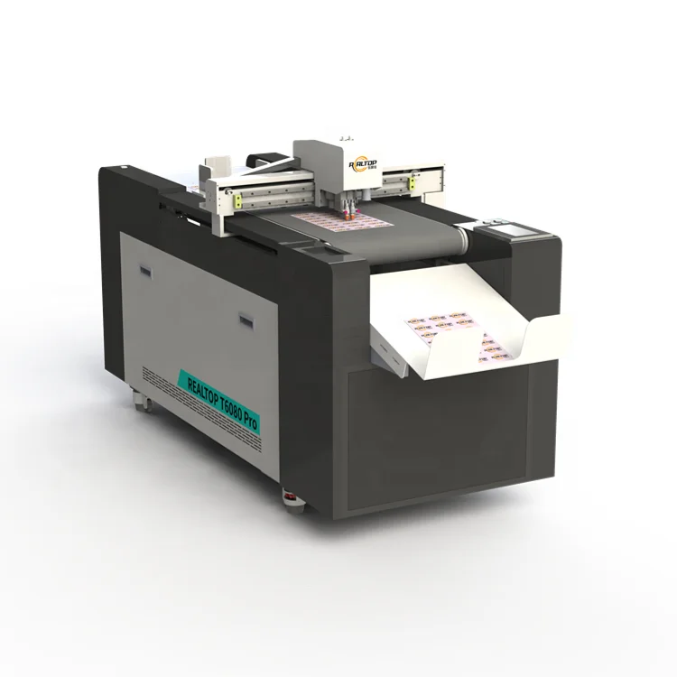
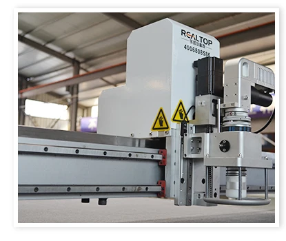
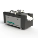
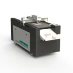
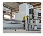
| Product Type | CNC Oscillating Knife Cutting Table |
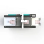
| Working Area | 1600 × 2500 mm |
| Machine Size | 3450 × 2300 × 1250 mm |
| Rated Power | 9 kW |
| Table Type | Flat working table with vacuum adsorption |
| Vacuum Pump | 7.5 kW |
| Translational Velocity | 800–1200 mm/s |
| Cutting Speed | 200–800 mm/s (according to different cutting materials) |
| Repeated Accuracy | ≤0.1 mm |
| Cutting Thickness | ≤100 mm (varies with the material) |
| Transmission System | Digital servo motor, linear guide, synchronous belt, ball screw |
| Visual Positioning | Small CCD camera mark point positioning; panoramic camera recognition; projection positioning |
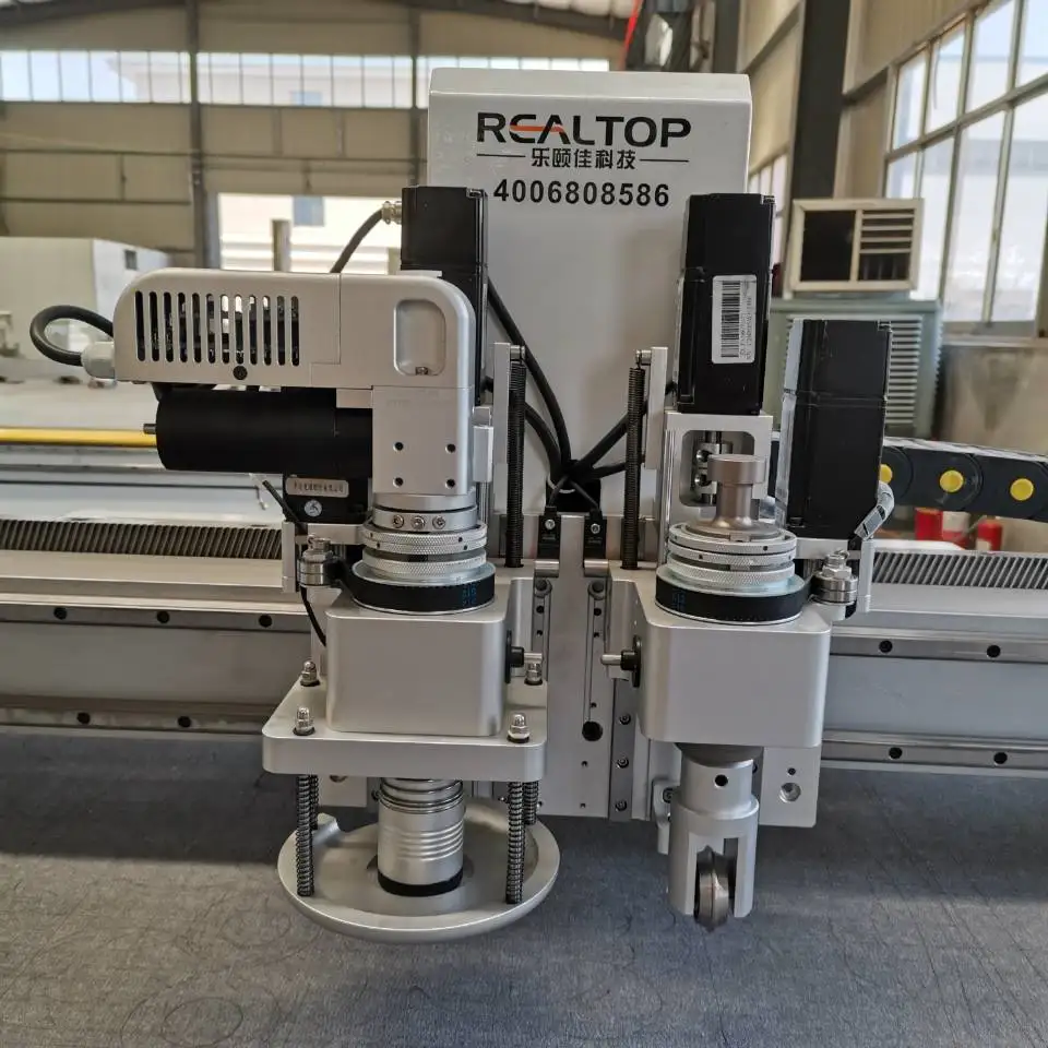
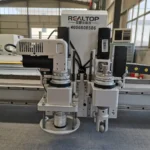
| Multifunctional Head | Swiss imported knife with vibration full cutting, half cutting and cursor location |
| Tool Head Options | Oscillating knife, pneumatic knife, high-power vibrating knife, circular knife, V-cutting knife, drag knife, creasing wheel, dotted line knife, punching, brush |
| Safety Device | Infrared sensors |
| Instruction System | HP-GL compatible format |
| Voltage | 380V ±10% |
| Control Language Options | English, Russian, Italian, Chinese, etc.; special languages customizable |
| Other Configuration | Delta servo motor, Germany imported conveyor belt, auto feeding, Taiwan Hiwin rail |
| Standards | CE declaration where applicable |
Application Suitability
| Application | Material or Output |
|---|---|
| Garment and footwear production | Clothing cloth, shoe material, leather, sponge composite leather, non-woven fabric |
| Automotive interior trimming | Carpet, floor mat, PU, EVA, XPE foam, gasket material |
| Packaging sample making | Corrugated cardboard, sticker, film, plastic box |
| Soft furnishings and textiles | Fabric, textile, carpet, leather, PU, PVC |
| Composite and sealing fabrication | PTFE, ETFE, fiberglass, rubber, silicone, soft glass |
| Graphic advertising and printing | Vinyl, sticker, film, board |
Why Generic "Cutting Thickness" Numbers Mislead Buyers
A machine rated to cut 100 mm of foam will not necessarily cut 100 mm of corrugated board with the same tool head. The stated cutting capacity varies with material density, fibre direction and hardness. When buyers focus only on the headline thickness without confirming the tool head and oscillation frequency against their actual stock, the result is ragged edges, crushed layers or blade wear that forces constant stoppages [NEED_CITE: oscillating knife cutting depth variation by material type].
I once watched a buyer specify a vibrating knife for five-layer corrugated cardboard based on a sample cut that used much softer stock. The blade dulled within two shifts and the daily throughput fell well below expectation. That is why we run sample cutting on the buyer’s own material before finalising the configuration, so the oscillating knife cutting table specifications match the real production environment rather than a lab sample.
Matching the Knife Type to the Fibre Structure
Each tool head in the multifunctional carriage addresses a different cutting action. The Swiss imported oscillating knife handles vibration full cutting and half cutting, suitable for dense textiles and leather where a clean shear is needed. The drag knife suits thinner films and stickers. The creasing wheel scores corrugated cardboard without severing the flute structure, which is essential for packaging sample making. Selecting the wrong head for the stock produces either incomplete cuts or torn edges.
Vacuum Zoning and Small-Part Hold-Down
The magnesium-aluminium alloy vacuum table paired with the 7.5 kW vacuum pump provides uniform suction across the 1600 × 2500 mm working area. Zoning matters when nesting small gaskets or garment pattern pieces, because a single-zone table can lose suction at the far end, causing parts to lift during high-speed translation [NEED_CITE: vacuum table zoning requirements for nested small parts in digital cutting]. The auto-feeding system with the Germany imported conveyor belt keeps material flat as new sheets advance into the cutting zone.
Reading the Specs That Actually Govern Edge Quality
Translational velocity of 800–1200 mm/s tells you how fast the carriage moves between cuts, but the cutting speed of 200–800 mm/s governs the actual blade engagement with the material. Repeated accuracy of ≤0.1 mm, achieved through the Delta servo motor and Taiwan Hiwin linear rail, determines how closely nested pieces follow the intended path — critical when cutting gaskets that must seat against machined flanges. The HP-GL compatible instruction system ensures that DXF and PLT files from common nesting software import without manual rework. Voltage at 380V ±10% requires confirmation against the buyer’s local supply, and the control language must be set before the machine leaves the factory to avoid commissioning delays on site.
The Cost of Skipping the Material Trial
Buyers who approve a configuration from a catalogue drawing alone often discover during installation that the vacuum zoning cannot hold their smallest nested parts, the CCD camera cannot track printed marks at full cutting speed, or the oscillation frequency crushes their foam instead of shearing it. These issues surface only when the machine meets the actual stock at production pace, and correcting them after shipment means waiting for replacement tool heads and re-commissioning the table [NEED_CITE: common commissioning issues with digital cutting tables after shipment].
What You Verify Before the Crate Is Sealed
Tool head selection is confirmed against your material sample, not a generic recommendation. The vacuum table zoning is mapped to your nesting layout so suction reaches the smallest part. CCD camera positioning is tested with your printed artwork to confirm mark recognition at production speed. Electrical schematics and voltage are matched to your facility supply. Software compatibility is checked against your existing DXF or HP-GL files before the control system is locked for shipment.
Documentation & Verification
- Machine specification sheet listing the exact tool heads and vacuum zoning fitted to your table
- Electrical schematic confirming 380V ±10% wiring and plug type for your destination market
- Sample cutting report on your own material documenting edge quality and achievable cutting speed
- Tool head and table configuration list matched to your material type and thickness range
- Software licence and file format compatibility note for HP-GL import and nesting workflow
- Factory test record and packing photographs taken before the crate is closed
Installation, Commissioning & Support
- Floor space of at least 3450 × 2300 mm with level concrete slab to support the flat working table
- Dedicated 380V ±10% circuit with correct phase sequence for the 9 kW rated power draw
- Machine ships partially assembled; table frame, gantry and carriage require on-site alignment
- First-run parameter setting includes vacuum zoning calibration, servo tuning and CCD mark registration
- Operator training covers tool head changeover, blade replacement and nesting file import procedures
- Spare parts list includes Swiss knife blades, drag knife tips and vacuum table seals for routine maintenance
What We Need to Specify Your Table Correctly
Send us a representative sample of the material you will cut most often, along with its thickness and the smallest piece in your nesting layout. Tell us your local voltage and frequency, the control language your operators need, and whether your workflow uses DXF, HP-GL or another file format. If your production involves printed contour work, share a printed sheet so we can test CCD recognition before you commit.
Frequently Asked Questions
Q: How do I choose between oscillating knife, drag knife and creasing wheel for my material?
A: Oscillating knives shear through thick, fibrous stock like fabric and foam cleanly. Drag knives suit thin films and stickers where a drawn cut is sufficient. Creasing wheels score corrugated board without cutting through the flute. We test each option on your material sample and recommend the head that gives the edge quality your product requires.
Q: Will the vacuum table hold very small nested parts without lifting?
A: The 7.5 kW vacuum pump paired with zoned suction on the magnesium-aluminium table is designed to maintain hold-down across the full 1600 × 2500 mm area. We map the zones to your nesting layout during configuration so that even small gasket or pattern pieces stay flat at cutting speed.
Q: Can the CCD camera track printed marks at full production speed?
A: The small CCD and panoramic camera options both support mark-point and contour recognition. We verify tracking performance using your actual printed material before shipment, confirming that the camera registers marks reliably at the cutting speed your stock allows.
Q: Will my existing DXF and HP-GL files work without modification?
A: The control system accepts HP-GL compatible format directly. We test your existing files and nesting software output before dispatch and note any required adjustments in the software compatibility document so your workflow transfers without rework.
Q: How are voltage, plug type and control language confirmed before shipment?
A: We request your facility voltage, frequency and plug standard at the order stage, then verify the electrical schematic matches. The control language is set and tested in the requested language during the factory run, so the interface is ready when the machine arrives on your floor.


商品评价
Clear filtersThere are no reviews yet.