


Fast Shipping
Carrier information

20k products
Payment methods

24/7 Support
Unlimited help desk

2-day Delivery
Track or off orders
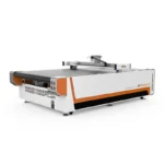
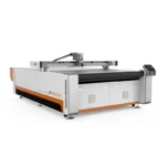
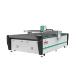
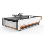
Specified per material stack — The RT-D2516/RT-S2516 matches oscillating knife, drag knife, or creasing tool heads to your exact fabric, leather, or foam thickness rather than defaulting to a single blade type.
Technical Specifications
| Parameter | Value |
|---|---|
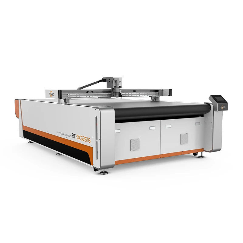
| Model | RT-D2516 / RT-S2516 |
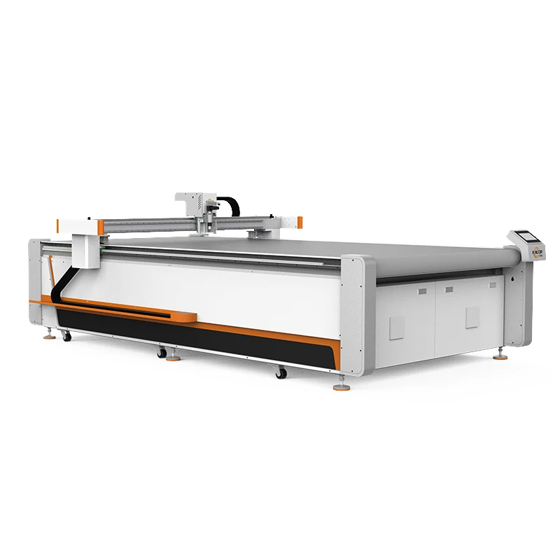
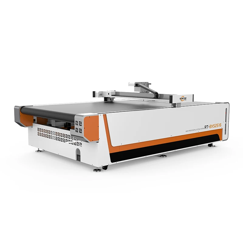
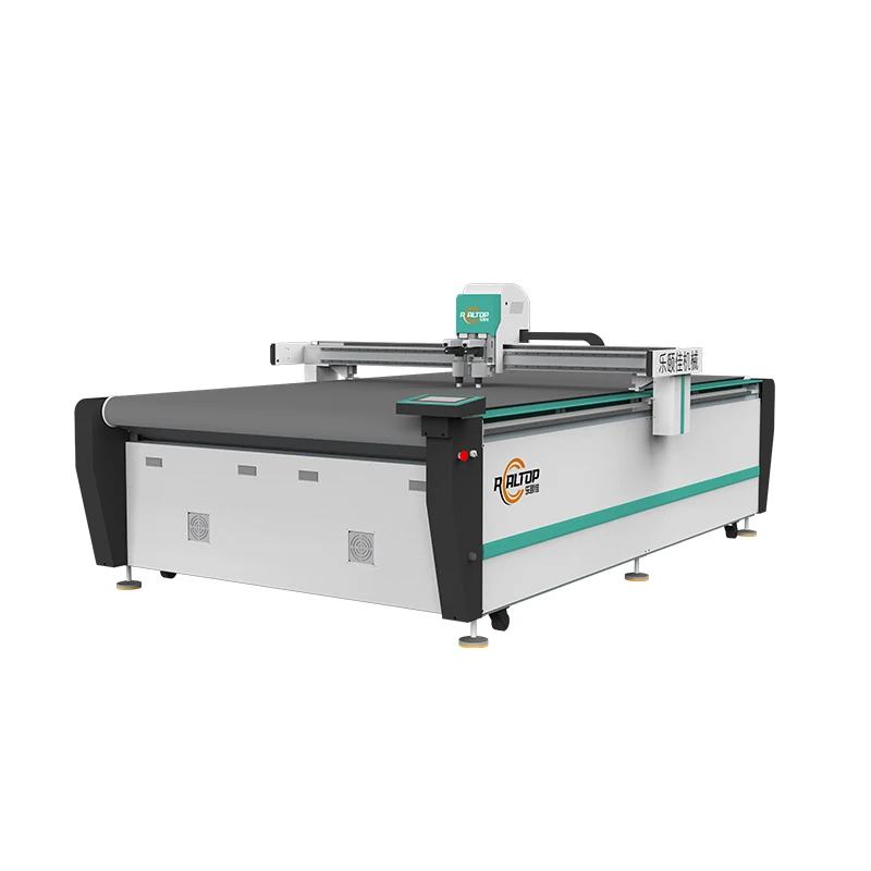
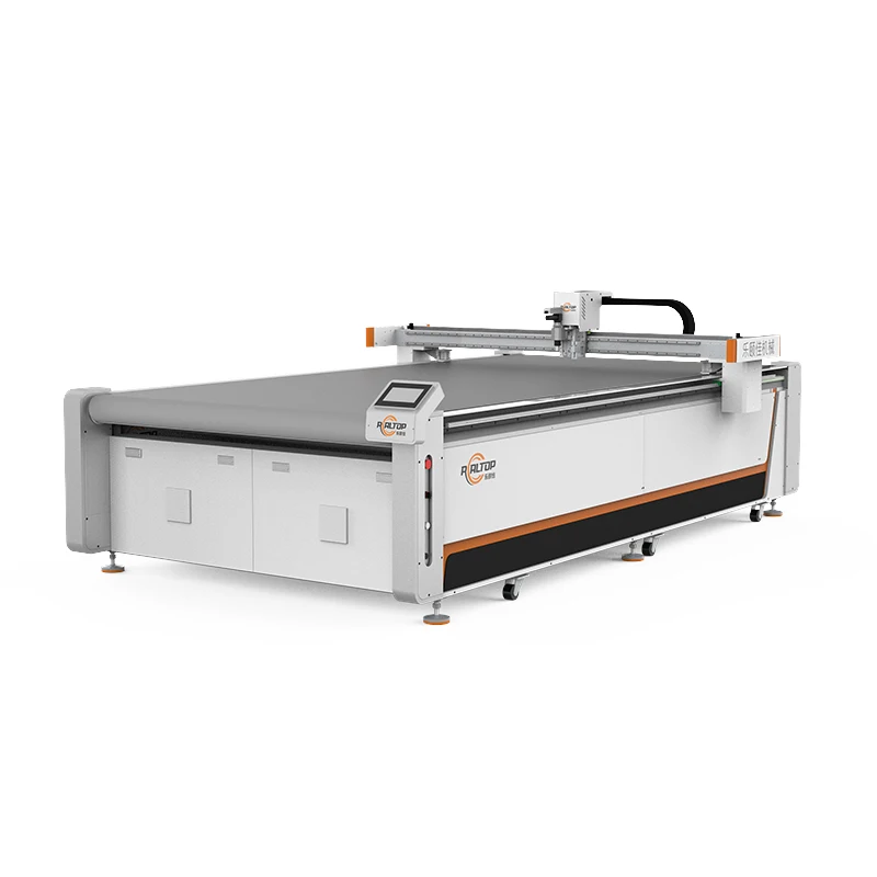
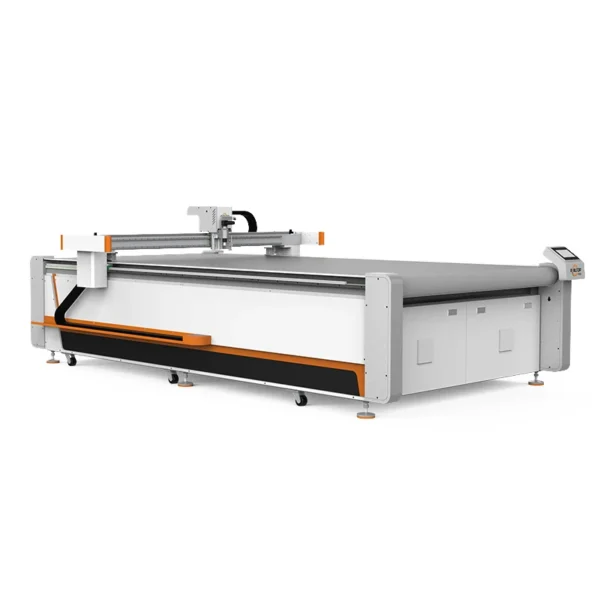
| Product Type | CNC Oscillating Knife Cutting Machine |
| Working Area | 1600 × 2500 mm |
| Overall Dimensions | 3450 × 2300 × 1250 mm |
| Rated Power | 9 kW |
| Voltage | 380V ±10% (configurable) |
| Translational Velocity | 800 – 2000 mm/s |
| Cutting Speed | 200 – 800 mm/s (varies by material) |
| Repeatability | ≤ 0.1 mm |
| Transmission System | Digital servo motor (Delta / Panasonic optional), Taiwan Hiwin linear guide, ball screw, synchronous belt |
| Vacuum Pump | 7.5 kW, aviation aluminum shell with built-in silencer sponge |
| Vacuum Table | Magnesium-aluminum alloy, fluorocarbon PVDF sprayed, anodic and hard oxidation treated |
| Tool Head Options | Oscillating knife, pneumatic knife, high-power vibrating knife, circular knife, V-cutting knife, drag knife, creasing wheel, dotted line knife, punching, brush |
| Visual Positioning | Small CCD mark point positioning, panoramic camera recognition, projection positioning |
| Control Format | HP-GL compatible |
| Software File Support | PLT, DXF, AI |
| Control Panel | Touch screen, multi-language (English, Russian, Italian, Chinese; special languages customizable) |
| Conveyor Belt | Germany imported |
| Safety Devices | Infrared induction blocking, anti-collision sensors, emergency stop |
| Table Type | Flat working table or auto feeding table (configuration dependent) |
Application Suitability
| Application | Material or Output |
|---|---|
| Automotive interiors | Car mats, leather seat covers, gasket materials, sound-deadening composites |
| Garments and footwear | Multi-layer fabric panels, upholstery textiles, synthetic leather uppers |
| Bags and luggage | PU leather, nylon, canvas, reinforcement boards |
| Soft home furnishings | Curtain panels, sofa upholstery, carpet and floor mat contours |
| Packaging and carton sample making | Corrugated board, cardboard, foam board prototypes |
| Gaskets and sealing pads | Rubber, PTFE, ETFE, non-woven fabric, composite sheets |
| Advertising and signage | PVC foam board, sticker film, vinyl, acrylic templates |
Why "Cutting Thickness ≤ 100 mm" Is Not the Whole Story for CNC Oscillating Knife Cutting Machine Specifications
Actual usable depth depends on blade stroke, material density, and vacuum hold-down — not just the number on the spec sheet.
I once watched a production line stall because a quoted maximum thickness assumed a soft, low-density foam while the real material was a dense, two-layer automotive leather composite. The blade deflected, edges turned ragged, and daily output dropped sharply before the issue was traced back to configuration mismatch. When buyers evaluate CNC oscillating knife cutting machine specifications, a single thickness figure without material context creates false expectations. Confirming the cutting depth on your actual material stack — with the correct tool head and vacuum zoning — removes that risk before the machine ships [NEED_CITE: material density effects on oscillating knife penetration and edge quality].
Tool Head Selection Dictates Edge Quality on Every Material
The RT-D2516/RT-S2516 supports a multifunctional head carrying Swiss-imported blades, and the available tool options — oscillating knife, drag knife, creasing wheel, punching, and more — exist because no single blade geometry handles fabric, foam, and corrugated board equally well. An oscillating knife delivers a clean shear cut through woven textiles and leather, while a drag knife suits thin vinyl and sticker film. Selecting the wrong head produces frayed edges or crushed foam cores, regardless of how accurate the motion system is.
CCD Camera Positioning at Production Speed
When your parts are printed with contour marks, the camera must register and adjust the cut path before the material advances. The RT-D2516/RT-S2516 offers small CCD mark point positioning, panoramic camera recognition, and projection positioning as selectable options. Panoramic recognition captures a wider field, reducing the number of fiducial marks needed per sheet, while projection positioning lets operators visually verify alignment before the blade engages. Choosing the right CNC oscillating knife cutting machine configuration for your print-to-cut workflow prevents misregistration waste on high-volume runs [NEED_CITE: CCD registration accuracy requirements for printed textile and signage cutting].
Reading the Specs That Actually Affect Your Output
The 1600 × 2500 mm working area accommodates standard fabric rolls and leather hides without excessive re-clamping. Translational velocity of up to 2000 mm/s governs non-cutting travel, while the 200–800 mm/s cutting speed range reflects material-dependent feed rates — denser composites require slower passes to maintain ≤ 0.1 mm repeatability. The 7.5 kW vacuum pump paired with the magnesium-aluminum PVDF-treated table delivers uniform suction across the surface. Proper vacuum zoning matters when cutting small gasket parts that might otherwise lift off the table mid-pass. Taiwan Hiwin linear guides and Delta or Panasonic servo motors maintain positioning accuracy over extended production shifts.
The Cost of Skipping Material-Specific Configuration
A machine ordered on working area alone, without confirming tool head and vacuum zoning against your actual material, shows its weaknesses only after installation. Small parts lift during cutting, edges crush instead of shearing, and operators spend time manually adjusting feed rates that should have been preset. In fabric and leather applications, these issues compound across hundreds of panels per shift, turning a capacity investment into a bottleneck. Verifying configuration on sample material before the order is placed eliminates most of these downstream failures [NEED_CITE: vacuum table zoning effectiveness for small-part CNC knife cutting].
Why Production Teams Source This Platform
In-house design covers both knife and laser cutting methods, so the cutting process matches the material rather than forcing one technology across dissimilar substrates. Tool head and table configurations are specified per your material type and daily volume, not left as a default package. CCD camera positioning is confirmed against your print registration marks before the order is finalized. Software compatibility with PLT, DXF, and AI file formats is verified alongside your existing nesting workflow. Voltage, plug type, and control panel language are locked in before production begins. Sample cutting on your own material provides a documented report showing edge quality and achievable thickness before commitment.
Documentation & Verification
- Machine specification sheet listing confirmed tool head and vacuum table configuration
- Electrical schematic with voltage and frequency matched to your facility
- Sample cutting report produced on your material showing edge quality and depth
- Factory test record documenting repeatability and CCD positioning accuracy
- Software licence and file format compatibility note for your nesting workflow
- Spare parts list with Swiss-imported blade specifications and replacement intervals
Installation, Commissioning & Support
- 3450 × 2300 mm footprint requires level floor with clearance for auto feeding table conveyor
- Dedicated 380V ±10% circuit rated for 9 kW continuous draw plus 7.5 kW vacuum pump
- Machine ships in sectional form; vacuum table and gantry assembled on-site
- First-run parameter setting includes vacuum zoning mapped to your typical part sizes
- Operator training covers tool head changeover and CCD camera calibration procedures
- Spare blade and belt inventory specified to match your production shift schedule
What to Prepare Before Requesting a Quote
To size the configuration accurately, share your material type, maximum thickness, and whether you run single-layer or multi-layer stacks. Confirm your local voltage and frequency, preferred control panel language, and whether your workflow uses printed contour marks that require CCD positioning. If you run existing nesting software, provide a sample file so format compatibility is verified before the order is finalized.
Frequently Asked Questions
Q: How is cutting thickness verified for my specific material and stack height?
A: A sample cutting test is run using your actual material at the thickness and layer count you intend to produce. The report documents which tool head was used, the achieved edge quality, and the maximum clean-cut depth confirmed. This removes guesswork from the specification and ensures the CNC oscillating knife cutting machine is configured for your real production conditions before it ships.
Q: Which tool head is right for my material — oscillating, drag, creasing, or punching?
A: Oscillating knives shear through woven fabric, leather, and foam cleanly. Drag knives suit thin films and sticker vinyl. Creasing wheels score corrugated board without cutting through. Punching tools create holes and slots in gasket materials. The correct head is selected during the sample cutting phase and listed in your configuration document, so the machine arrives with the right tools for your primary materials.
Q: Can the CCD camera track printed contour marks at full production speed on my material?
A: Yes, provided the correct camera option is matched to your mark size and print contrast. Panoramic recognition covers a wider field for fewer marks per sheet, while mark point positioning suits smaller, high-contrast fiducials. The camera system is tested on your printed material during the sample phase to confirm reliable tracking before the configuration is finalized.
Q: How is vacuum table zoning configured to prevent small parts from lifting during cutting?
A: The magnesium-aluminum table surface is divided into independently controlled vacuum zones. Zones beneath your typical part footprint are activated while surrounding areas are closed, concentrating suction where it is needed. Zone layout is mapped during commissioning based on your most common part sizes, ensuring small gaskets and fabric pieces stay flat throughout the cut cycle.
Q: What voltage, plug type, and control language are confirmed before shipment?
A: Your facility voltage and frequency are verified during the specification phase, and the electrical schematic reflects the confirmed values. Plug type matches your local standard. The touch-screen control panel is set to your preferred language — English, Russian, Italian, Chinese, or a custom language arranged before production. All three items are documented in the pre-shipment confirmation file.


商品评价
Clear filtersThere are no reviews yet.