







Fast Shipping
Carrier information

20k products
Payment methods

24/7 Support
Unlimited help desk

2-day Delivery
Track or off orders
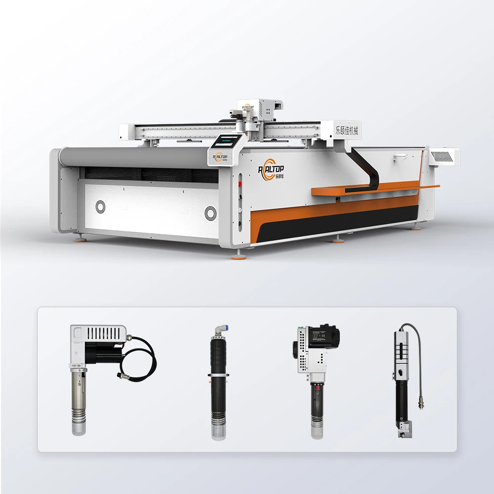
Tool-Head Versatility — Seven interchangeable cutting heads let you switch from oscillating knife on woven stacks to driven rotary knife on non-woven rolls without swapping the base machine.
Technical Specifications
| Parameter | Value |
|---|---|
| Product Type | CNC Oscillating Knife Cutting Machine |
| Working Area | 1600 * 2500 mm |
| Cutting Tools | Oscillating knife, Driven rotary knife, Creasing wheel, Kiss cutting tool, Pneumatic knife, Milling tool, V groove knife |
| Cutting Speed | 0 – 2000 mm/s |
| Cutting Thickness | ≤ 30 mm |
| Cutting Accuracy | ±0.1 mm |
| Vacuum Pump | 9 kW |
| Vacuum Table | Aluminum bellows vacuum table |
| Servo Motor Options | Panasonic, Delta, Dorna |
| Voltage Options | 110V, 220V, 380V |
| Control System | PLC control panel (source value — verify against manufacturer catalog) |
| Profile Formats | PLT, DXF, AI, PDF |
| Safety Features | Infrared sensor device, emergency stop device |
| Machine Size | 3300 2100 1350 mm |
| Language Options | English, Russian, Italian, Chinese (customizable) |
| Certification | CE (verify against actual certificate) |
Application Suitability
| Application | Material or Output |
|---|---|
| Apparel manufacturing | Suits, knitwear, lace, and complex woven fabrics in multi-layer stacks |
| Automotive interiors | Seat fabrics, carpets, and PVC mats requiring burr-free edges |
| Home textiles | Sofa fabrics, curtains, and rugs with pattern-matching requirements |
| Composite processing | Carbon fiber prepreg and aramid sheets for structural components |
| Textile and non-woven cutting | Multi-layer stacks of non-woven fabric up to 30 mm compressed thickness |
Why Tool Head Selection Matters More Than Cutting Speed
The wrong tool head on the right machine still ruins the material.
I have watched garment factories in Latin America run an oscillating knife through loosely woven knits and end up with frayed edges on every piece, simply because a driven rotary knife would have sliced cleanly through the same stack. Buyers often fixate on the top travel speed printed on a brochure, yet the CNC oscillating knife cutting machine specifications that determine actual output quality start at the tool holder, not the servo motor [NEED_CITE:]. When the tool geometry does not match the fabric behavior under compression, you get ragged edges, delaminated layers, or crushed foam cores that fail downstream inspection regardless of how fast the gantry moves.
Matching Knife Geometry to Fabric Behavior
An oscillating knife works well on dense, compressed stacks of woven material where a straight vertical stroke separates fibers cleanly through the full depth. A driven rotary knife, however, cuts with a rolling shear action that grips the top layer and pulls it through, making it better suited for non-woven rolls and single-ply technical textiles where edge sealing matters. A pneumatic knife provides additional downward force for thicker foam and gasket materials that resist standard oscillation. Selecting the correct tool head from the seven available options ensures the cutting action matches the fiber structure, which is the single most important CNC oscillating knife cutting machine specifications decision a textile buyer makes.
Vacuum Zoning Across the Full Bed Area
The aluminum bellows vacuum table on this system covers the full 1600 by 2500 mm working area, but full-surface adsorption is not always the right approach. When cutting small garment pattern pieces from a multi-layer stack, the vacuum zones must be selectively activated so that only the area under the cutting head holds the material down. Without proper zoning, small cut pieces lose suction once separated and shift under the gantry, producing mis-cut parts that are only discovered after the entire nest has been processed [NEED_CITE:]. The 9 kW vacuum pump provides sufficient suction for dense woven stacks, but zoning configuration must be confirmed against your typical pattern layout and piece size before the table is built.
Interpreting the Numbers That Actually Affect Production
The ±0.1 mm cutting accuracy specification refers to repeat positioning accuracy of the gantry and head assembly, which determines how closely nested pieces align across a full bed run. For multi-layer garment cutting where thirty or more plies are stacked, this tolerance ensures that the bottom layer matches the top layer within acceptable pattern grading limits. The 0-2000 mm/s speed range is the maximum travel speed of the gantry; actual cutting speed depends on material density, layer count, and the tool head selected. Cutting thickness of up to 30 mm refers to the compressed stack height the oscillating knife can penetrate in a single pass, which varies depending on fabric density and how much the material compresses under vacuum pressure. The available servo motor options, Panasonic, Delta, or Dorna, affect long-term positioning consistency and spare part availability in your local market, which matters when a motor needs replacing two years after installation.
The Cost of Skipping the Material Sample Test
A buyer in Mexico once ordered a multi-layer cutting system based on the rated layer count alone, assuming his local non-woven fabric would behave like the standard test material. When the machine arrived, the non-woven was heavier and less porous than expected, so the vacuum table could not hold the stack flat and the material shifted during cutting. An entire roll of production was scrapped before the problem was diagnosed. This failure would have been caught by a sample cutting test on the buyer’s actual fabric before the order was confirmed, which is why sending material samples to the factory is a non-negotiable step in the purchasing process [NEED_CITE:]. The cost of shipping a few meters of fabric to the factory is insignificant compared to the cost of receiving a machine configured for the wrong material.
How the Factory Builds Around Your Material
The design team configures the tool head combination, vacuum zone layout, and blade oscillation frequency based on the specific fabric samples received from the buyer, rather than shipping a standard configuration and hoping it works. Every machine undergoes a factory test using the buyer’s actual material before crating, with cutting results documented and shared for approval. The CCD camera contour recognition system is calibrated to the specific printed mark style and color contrast used on the buyer’s fabric, ensuring reliable tracking at production speed. Voltage, plug type, and control panel language are confirmed against the buyer’s local electrical standards and operator requirements before production begins. Software licensing and file format compatibility with the buyer’s existing nesting workflow, whether DXF, PLT, AI, or PDF, is verified so there are no integration delays on arrival.
Documentation & Verification
- Machine specification sheet matching the agreed tool head and vacuum configuration
- Sample cutting report on buyer’s own fabric with measured edge quality and accuracy
- Electrical schematic confirming voltage, plug type, and circuit requirements
- Factory test record showing cutting performance on the specific material submitted
- Software license documentation with confirmed file format compatibility
- Spare parts list identifying consumable blades and vacuum table seals
Installation, Commissioning & Support
- Floor space allocation for the 3300 by 2100 mm footprint with clearance on all sides
- Dedicated electrical circuit matching the confirmed voltage and the 9 kW vacuum pump draw
- Assembly of the aluminum bellows vacuum table sections and vacuum line connections
- First-run calibration of the selected tool heads on the buyer’s actual production material
- Operator training on tool head changeover, vacuum zoning adjustment, and CCD alignment
- Scheduled maintenance plan for blade replacement intervals and vacuum pump filter cleaning
What We Need From You to Quote Correctly
Send us a sample of the fabric you will be cutting, including the typical stack height and whether the material has printed contour marks. Confirm the voltage and frequency at your facility, the control panel language your operators require, and the nesting software you currently use so we can verify file format compatibility. If you have a daily production volume target, share that along with your typical pattern layout so we can recommend the right vacuum zone configuration.
Frequently Asked Questions
Q: How do I choose between the oscillating knife and driven rotary knife for my fabric?
A: The oscillating knife suits dense woven stacks where a vertical stroke cuts cleanly through compressed layers. The driven rotary knife works better on non-woven rolls and single-ply technical textiles where a rolling shear action produces sealed edges. Send a fabric sample and we test both to confirm which delivers the cleanest cut on your material.
Q: Will the vacuum table hold small garment pieces once they are cut?
A: Small pieces lose suction if the entire table is under uniform vacuum. The aluminum bellows vacuum table supports zoning, where only the active cutting area holds the material. We configure the zone layout based on your typical pattern size so small parts stay flat until the full nest is complete.
Q: Can the CCD camera track printed marks on my fabric at full cutting speed?
A: CCD contour recognition depends on mark color, size, and contrast against the fabric background. We calibrate the camera to your specific print marks and test tracking at production speed during the factory sample run. If contrast is insufficient, we identify the issue before the machine ships rather than during installation.
Q: Will my existing DXF and PLT nesting files import directly?
A: The control system supports PLT, DXF, AI, and PDF profile formats. Before order confirmation, we test your actual nesting files on the software to confirm import compatibility and verify that layer assignment, cut order, and tool path logic transfer correctly without manual rework.


商品评价
Clear filtersThere are no reviews yet.