



Fast Shipping
Carrier information

20k products
Payment methods

24/7 Support
Unlimited help desk

2-day Delivery
Track or off orders
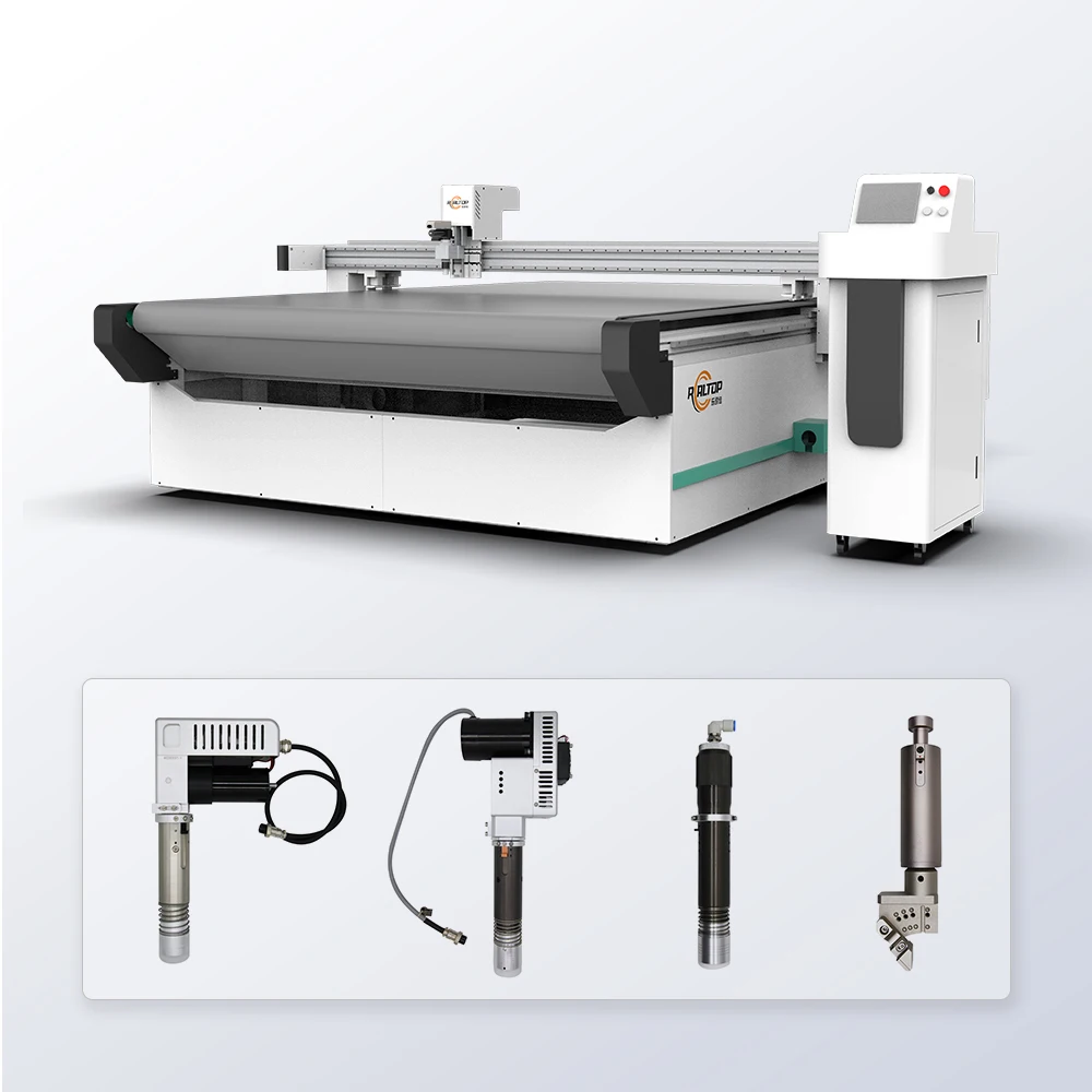
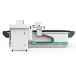
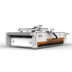
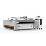
Configurable Cutting Head Array — every tool option from oscillating knife to creasing wheel is matched to your specific fabric weight, foam density, or gasket thickness before the machine ships.
Technical Specifications
| Parameter | Value |
|---|---|
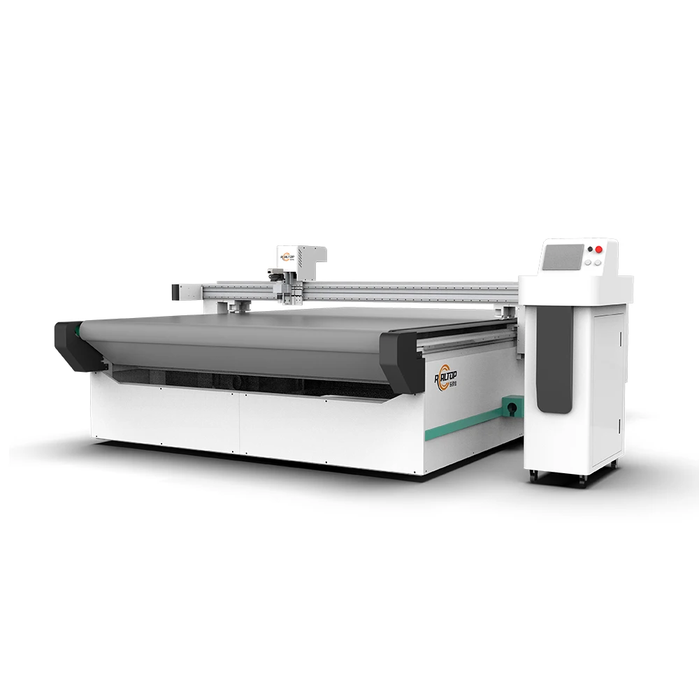
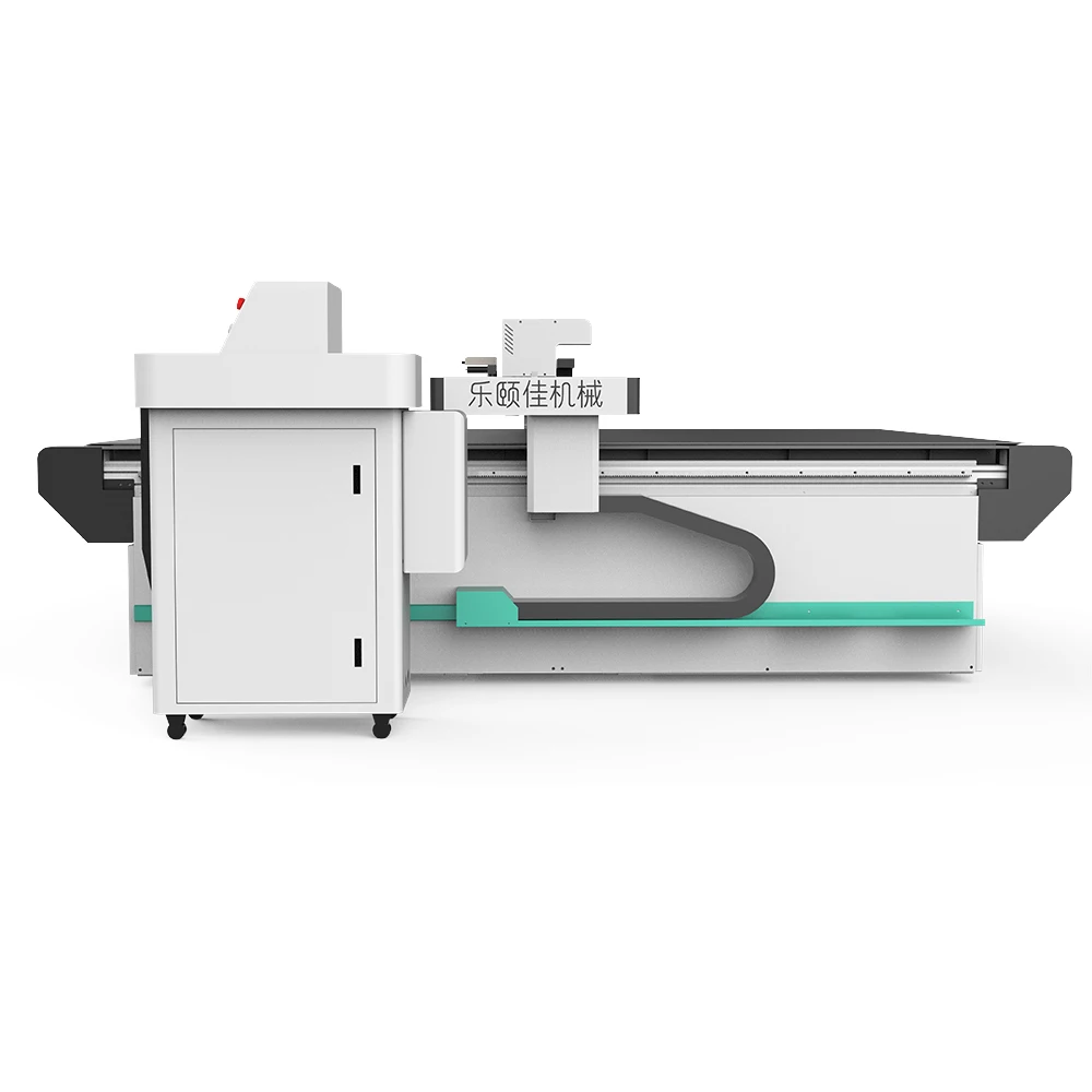
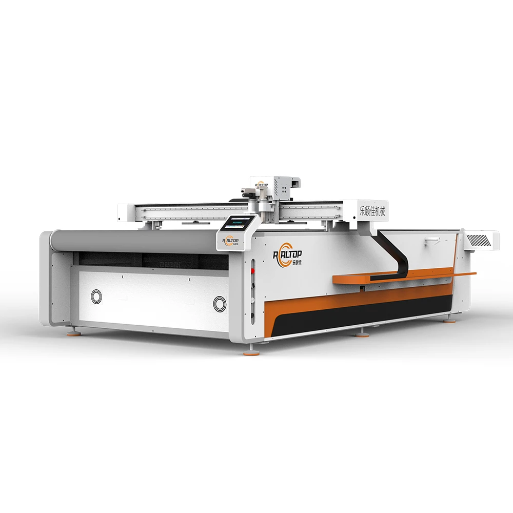
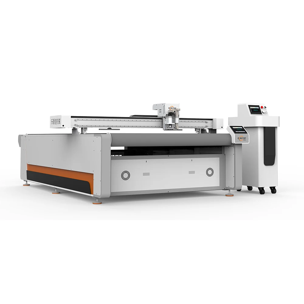
| Product Type | CNC Oscillating Knife Cutting Machine |
| Working Area | 1600 × 2500 mm |
| Machine Size | 3450 × 2300 × 1250 mm |
| Rated Power | 9 kW |
| Voltage | 380V ±10% |
| Vacuum Pump | 7.5 kW, integrated aviation aluminum shell with silencer |
| Table Type | Magnesium-aluminum alloy vacuum adsorption, PVDF powder sprayed, anodized; flat or auto-feeding configuration |
| Tool Head Options | Oscillating knife, pneumatic knife, high-power vibrating knife, circular knife, V-cutting knife, drag knife, creasing wheel, dotted line knife, punching, brush |
| Visual Positioning | Small CCD mark point, panoramic camera recognition, projection positioning |
| Translational Velocity | 800–2000 mm/s |
| Cutting Speed | 200–800 mm/s (basis to be confirmed by material, thickness, and layer count) |
| Cutting Thickness | ≤100 mm (varies with material density) |
| Repeated Accuracy | ≤0.1 mm |
| Transmission System | Digital servo motor (Delta or Panasonic optional, IP67), Taiwan Hiwin linear guide, synchronous belt, ball screw |
| Instruction System | HP-GL compatible format |
| File Format Support | PLT, DXF, AI |
| Safety Devices | Infrared induction blocking, beam anti-collision sensors, emergency stop with in-situ resume |
| Conveyor Belt | Germany imported |
| Control Panel | CNC touch screen, multi-language (English, Russian, Italian, Chinese; others customizable) |
| Assembly State | Fully assembled |
Application Suitability
| Application | Material or Output |
|---|---|
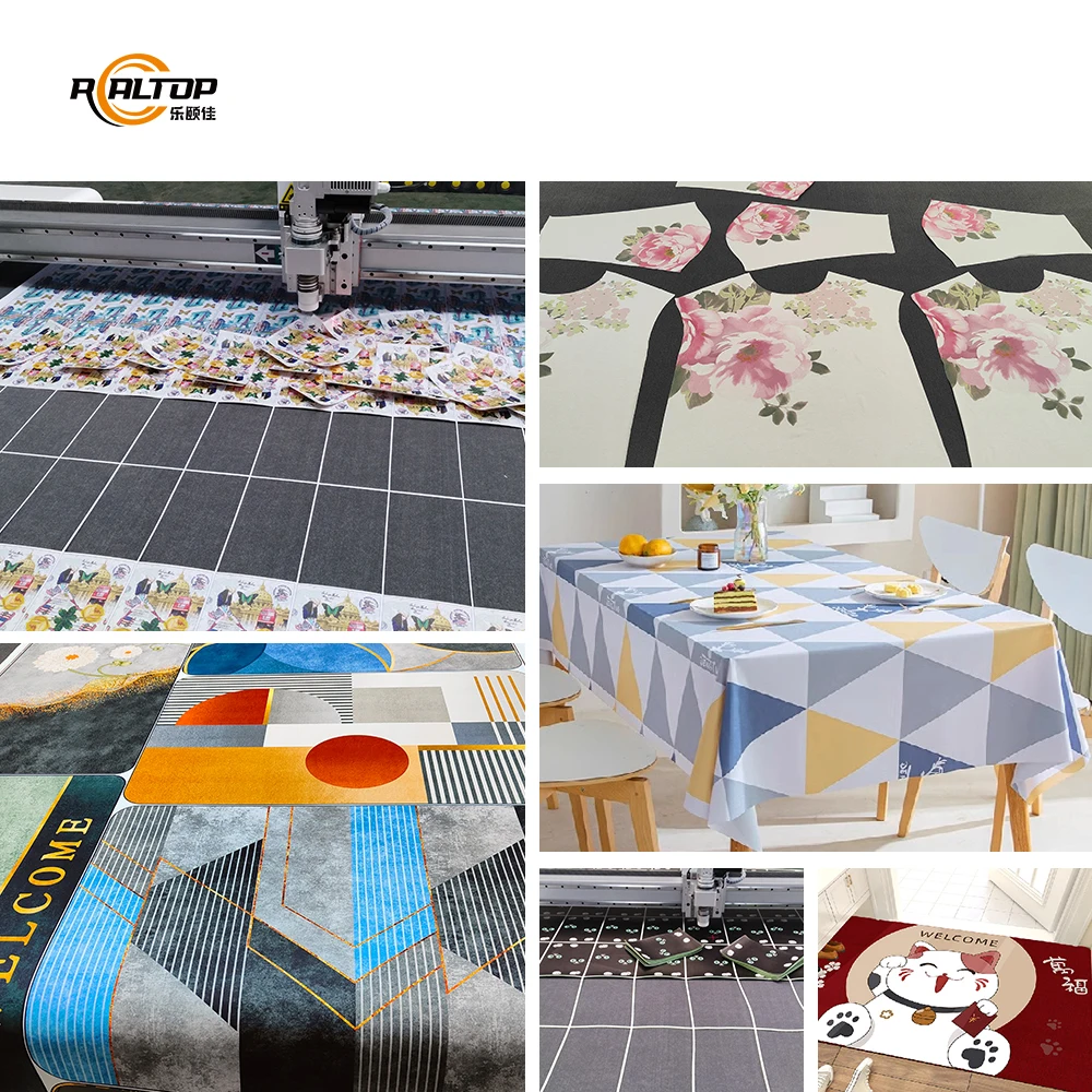
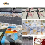
| Garment and footwear batch cutting | Single and multi-layer woven fabric, knit cloth, leather, PU, shoe lining material |
| Automotive interior trim production | Non-woven fabric, carpet, sponge, XPE foam, composite acoustic panels |
| Packaging and carton sample making | Corrugated cardboard, greyboard, plastic box stock with creasing and dotted-line scoring |
| Gasket and seal fabrication | PTFE, ETFE, rubber, PE, PP sheets requiring full cut and kiss cut |
| Graphic advertising and signage | PVC board, sticker film, vinyl, self-adhesive film on printed contour |
| Soft home furnishing | Curtain fabric, upholstery textile, carpet, EVA padding for sofa and mattress |
What Your Material Thickness Actually Demands from the Tool Head
The cutting thickness spec alone tells you nothing about edge quality on stacked layers.
Buyers often quote a maximum thickness number and assume any knife configuration handles it cleanly. I have watched production lines stall because a vibrating knife that sliced single-ply advertising banner perfectly could not penetrate a multi-layer quilted cotton stack without delaminating the batting [NEED_CITE: material layering effects on oscillating knife edge quality]. The oscillating frequency, blade profile, and downward pressure all shift when the material composition changes. A CNC oscillating knife cutting machine specifications sheet lists ≤100 mm, but the real question is whether your specific foam density or woven textile weight produces a clean edge at your target speed.
How Tool Head Selection Shapes Your Cut Quality
Different materials respond to different mechanical actions. An oscillating knife handles dense foam and thick gasket stock by vibrating the blade vertically thousands of times per minute, shearing through the material without dragging it. A drag knife suits thinner sticker and vinyl sheets where a continuous pull produces a clean contour. For corrugated sample making, the creasing wheel scores a fold line while the dotted-line knife creates tear-off perforations. Selecting the correct head prevents ragged edges, crushed foam cores, and delaminated composite layers.
Vacuum Table Zoning and Small Part Hold-Down
The magnesium-aluminum alloy table with PVDF coating provides a flat reference surface, but flatness alone does not hold a small gasket or leather patch in place during high-speed traversal. Vacuum zoning divides the working area into independently controlled sections so suction concentrates directly under the cut zone. Without adequate zoning, small parts lift off the table when the knife exits the material, producing dimensional drift or throwing the part into the beam path [NEED_CITE: vacuum hold-down requirements for small part CNC knife cutting].
Reading the Specs That Matter on the Shop Floor
Repeated accuracy of ≤0.1 mm depends on the entire transmission chain working within tolerance. Taiwan Hiwin linear guides maintain straightness across the 2500 mm travel, while the IP67-rated servo motors resist dust and coolant ingress common in textile and composite workshops. The 7.5 kW vacuum pump must generate sufficient negative pressure across the full 1600 × 2500 mm surface to prevent material shift during the 200–800 mm/s cutting stroke. If the vacuum pump is undersized relative to table area and material porosity — like an open-weave mesh fabric that bleeds air — the suction collapses and the material creeps.
When the Wrong Configuration Reaches Your Floor
I once reviewed a case where a buyer ordered a machine based on working area and assumed the standard oscillating knife would cover everything. Their actual production mix included thick EVA foam for sports insoles and thin PVC for blister packaging samples. The oscillating knife crushed the EVA at the cut entry point, leaving a compressed edge rather than a clean shear, and the drag knife tore the PVC film [NEED_CITE: tool mismatch consequences on multi-material cutting operations]. They had to order a second tool head and reconfigure the tool changer, delaying production by weeks. The configuration list must be locked against your full material range before the machine enters assembly.
Why Sourcing This Machine from a Knife-and-Laser Builder Matters
The manufacturer produces both knife and laser cutting systems in-house, so the recommendation on cutting method is driven by material behavior rather than limited to one technology. Every tool head and table configuration is specified against your material sample and daily volume before the order is confirmed. The CCD camera positioning options — mark point, panoramic, and projection — are tested with your actual printed registration marks at production speed. Voltage, plug type, and control panel language are documented in writing before shipment, avoiding the common scenario where a 380V machine arrives at a facility wired for a different supply standard [NEED_CITE: voltage mismatch incidents in industrial equipment import]. A sample cutting report on your own material accompanies the quotation so edge quality is verified before commitment.
Documentation & Verification
- Machine specification sheet listing confirmed tool head and table configuration per your material
- Electrical schematic with 380V ±10% wiring diagram and servo motor IP rating details
- Sample cutting report documenting knife type, speed, and edge outcome on your submitted fabric or foam
- Software licence with PLT, DXF, and AI file format compatibility confirmation
- Spare parts list covering blades, vacuum cups, and conveyor belt wear items
- CE declaration documentation where applicable to your import market
Installation, Commissioning & Support
- Machine arrives fully assembled at 3450 × 2300 × 1250 mm, requiring a level concrete floor with adequate clearance for the 7.5 kW vacuum pump exhaust
- Dedicated 380V ±10% circuit with correct breaker rating for the combined 9 kW machine and 7.5 kW pump load
- On-site commissioning includes vacuum zoning calibration matched to your primary material porosity
- CCD camera registration mark tuning verified with your printed artwork at target cutting speed
- Touch screen control language set to operator preference during training
- Blade replacement schedule and conveyor belt tensioning procedure documented in the operation manual
Before You Request a Quote
Send a physical sample of your primary material along with the maximum thickness, the number of layers you intend to stack, and your target daily cut volume. Specify your local voltage and frequency so the electrical system is configured before assembly. If you run printed contour work, provide a sample print with the registration mark format your existing workflow uses so the correct CCD positioning option is selected.
Frequently Asked Questions
Q: How do I decide between an oscillating knife and a drag knife for my material?
A: Oscillating knives suit dense or thick materials like foam, gasket stock, and multi-layer fabric where a vibrating vertical stroke shears cleanly without dragging. Drag knives work on thin, flexible sheets like vinyl and sticker film where a continuous pull follows contours. Submitting your material for a sample cut confirms which head produces the edge quality your product requires.
Q: The spec says cutting thickness up to 100 mm — does that apply to every material?
A: That figure is a general maximum that varies significantly with material density and composition. A 100 mm open-cell foam cuts differently from a 100 mm compressed rubber gasket. The only reliable way to confirm your material is cuttable at your required speed is a sample cutting test on your actual stock before the order is placed.
Q: Which CCD positioning option handles my printed contour work?
A: Small CCD mark point positioning tracks individual registration marks on each cut piece. Panoramic camera recognition captures the entire printed sheet for high-density nesting layouts. Projection positioning overlays the cut path onto the material for manual alignment verification. The correct choice depends on your mark format, print size, and production speed requirements.
Q: Will small gasket parts stay flat during high-speed cutting?
A: Vacuum zoning divides the table into independent suction sections, concentrating hold-down force under the active cut area. For very small parts, additional zoning configuration or a higher-porosity vacuum surface may be needed. This should be confirmed during the sample cutting stage using your actual part geometry and material.
Q: Can the software import my existing DXF and AI nesting files?
A: The system supports PLT, DXF, and AI file formats with HP-GL compatible instruction output. Before order confirmation, your specific nesting software export is tested for compatibility with the auto typesetting module to ensure file import, tool path assignment, and layer recognition function correctly in your production workflow.


商品评价
Clear filtersThere are no reviews yet.