




Fast Shipping
Carrier information

20k products
Payment methods

24/7 Support
Unlimited help desk

2-day Delivery
Track or off orders
Configured per material — tool head amplitude, vacuum zoning and CCD recognition are matched to your composite density and carpet backing thickness before the machine leaves the factory.
Technical Specifications
| Parameter | Value |
|---|---|
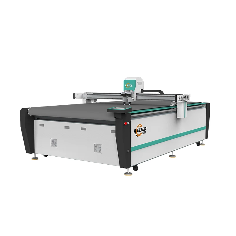
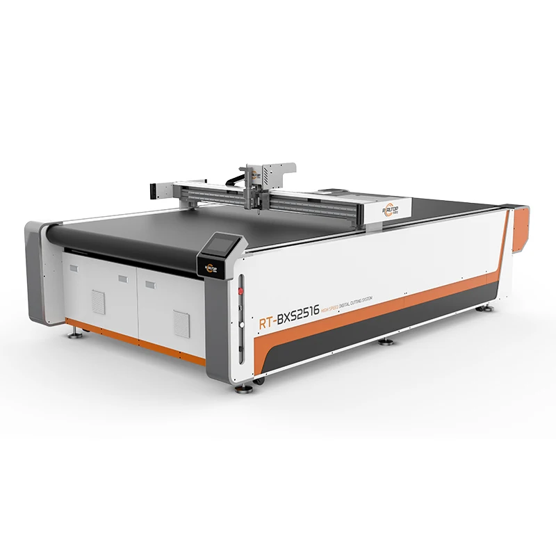
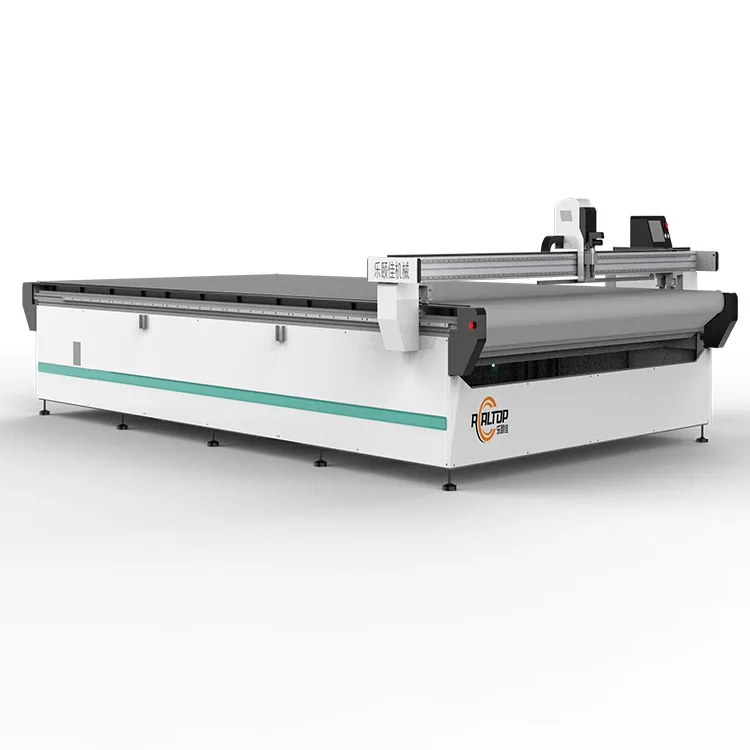
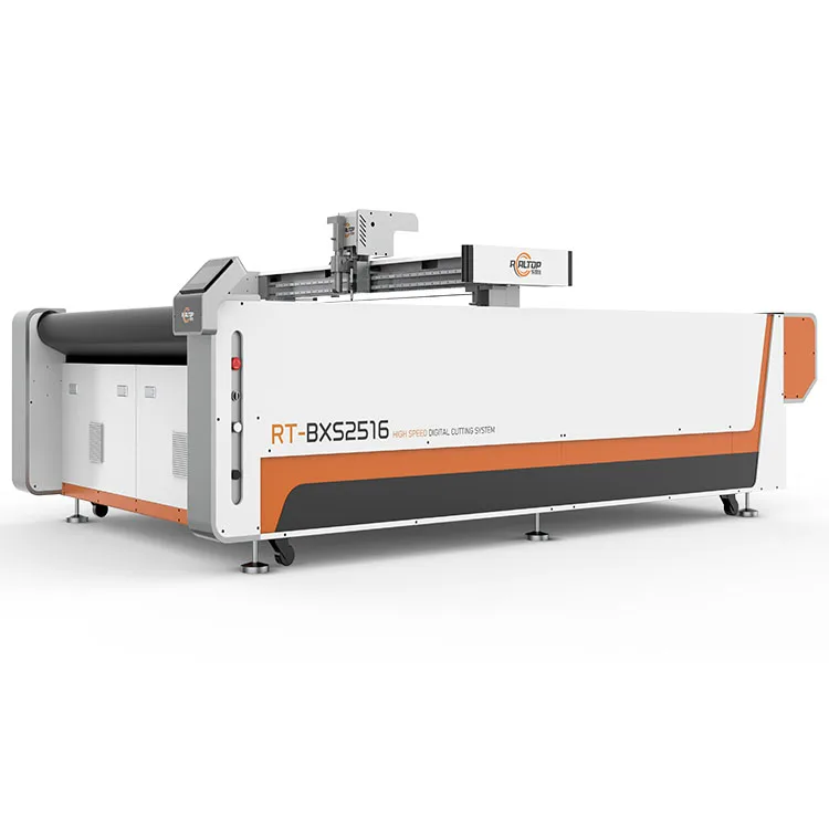
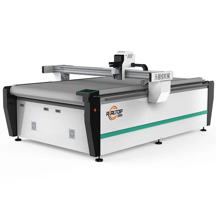
| Product Type | CNC Oscillating Knife Cutting Table with CCD Scanning System |
| Working Area | 1600×2500 mm |
| Machine Size | 3450×2300×1250 mm |
| Rated Power | 9 kW |
| Voltage | 380V±10% |
| Translational Velocity | 800–2000 mm/s |
| Cutting Speed | 200–800 mm/s (basis not stated in source) |
| Cutting Thickness | ≤100 mm (varies by material) |
| Repeatability | ≤0.1 mm |
| Working Table | Flat vacuum adsorption, magnesium-aluminum alloy with PVDF coating and anodizing |
| Tool Head Options | Swiss imported oscillating knife, pneumatic knife, high-power vibrating knife, circular knife, V-cutting knife, drag knife, creasing wheel, dotted line knife, punching, brush |
| Visual Positioning | Small CCD camera mark point positioning; panoramic camera recognition; projection positioning |
| Transmission System | Digital servo motor (Delta, optional Panasonic, IP67), linear guide, synchronous belt, ball screw (Taiwan Hiwin rail) |
| Vacuum Pump | 7.5 kW, integrated aviation aluminum shell with built-in silencer sponge |
| Conveyor | Germany imported conveyor belt with auto feeding |
| Instruction System | HP-GL compatible format |
| Safety Devices | Infrared induction blocking, anti-collision sensors on both sides of beam, emergency stop button with resume-in-situ function |
| Assembly State | Fully assembled |
| Standards | CE (verify per machine) |
Application Suitability
| Application | Material or Output |
|---|---|
| Printed carpet and floor covering cutting | Carpet rolls with printed contour, tracked by panoramic CCD camera |
| Composite panel cutting | Sponge composite leather, layered foam composites up to material-dependent thickness |
| Gasket and sealing production | PVC, soft glass, silicone and rubber sheets requiring drag knife or creasing wheel |
| Automotive interior trimming | Foam-backed fabric, headliner material and composite dashboard substrates |
| Packaging contour cutting | Corrugated board and carton sample sheets using CCD mark point positioning |
Why a Bigger Working Area Cannot Fix the Wrong Tool Head
Edge quality on layered composites is decided by tool head selection, not table size.
I have watched fabricators invest in a large-format flatbed, only to discover the oscillating knife amplitude was set for single-ply fabric while they were running 30 mm foam-backed composites. The blade deflects inside the material, leaving a ragged edge on the bottom ply and crushed cells in the foam core. A CNC oscillating knife cutting table for composites must be specified around the actual stack-up — density, adhesive layer, backing thickness — rather than the sheet dimension alone [NEED_CITE: oscillating knife amplitude selection for multi-layer composites]. When the carpet bottom glue turned out three millimetres thicker than the sample we tested, the original head pressure could not push through. We had to reconfigure on site, which cost the customer two weeks of production.
Multi-Head Tooling Matched to Composite Behaviour
The Swiss imported oscillating knife handles full cutting and half cutting on sponge composite leather and foam laminates, where a fixed drag knife would tear the bottom ply. For denser materials like rubber gaskets and silicone sheets, the drag knife or creasing wheel takes over without crushing the surface. Pneumatic and high-power vibrating knife options extend the range into thicker foam stacks. Each tool head is selected against the buyer’s sample material before configuration is locked, so the CNC oscillating knife cutting table for composites arrives with the correct cutting geometry already set.
CCD and Panoramic Camera Positioning for Printed Contours
Printed carpets and contoured composite panels rely on registration marks that shift with roll tension and humidity. The panoramic camera recognition system scans the full working area and adjusts the cutting path to match the actual print position, rather than assuming a fixed origin point. Small CCD mark point positioning handles tighter tolerances on gasket and packaging work. Projection positioning overlays the cut path onto the material surface, letting the operator verify alignment before the blade touches the sheet. This three-tier visual system means contour tracking remains reliable at production speed [NEED_CITE: CCD contour recognition accuracy on printed textile at line speed].
Reading the Specs That Actually Matter
The 7.5 kW vacuum pump paired with the magnesium-aluminum alloy PVDF-coated table is not just a suction figure — the zoning capability determines whether small gasket parts stay flat or lift during the final cuts. Repeatability at ≤0.1 mm across the 1600×2500 mm working area depends on the Taiwan Hiwin linear guides and IP67-rated servo motors holding position under the vibration of a high-power oscillating head cutting dense rubber. The 9 kW rated power covers the spindle, vacuum and conveyor running simultaneously; if your local supply cannot sustain 380V±10%, the servo drives will fault before the blade finishes a contour. The ≤100 mm cutting thickness ceiling varies with material density — a soft foam stack cuts at full depth while a dense rubber gasket may limit practical thickness well below that figure.
The Hidden Cost of Skipping Material Verification
When the vacuum table zoning is not matched to the smallest part in the nesting layout, those parts lift on the final pass and the blade catches the edge, ruining a panel that was ninety percent finished. Wrong tool head selection on layered composites produces delamination between the face fabric and the foam backing, which only shows up when the customer tries to sew or bond the cut piece downstream. Software that cannot import the buyer’s existing nesting files forces a manual redraw of every pattern, eliminating any throughput advantage the machine was supposed to deliver [NEED_CITE: file format compatibility issues in CNC cutting software adoption]. Voltage and plug mismatches discovered after shipment mean weeks of waiting for a step-down transformer while the machine sits unpowered on the factory floor.
Why Buyers Source This Equipment Here
In-house design covers both knife cutting and vacuum table engineering under one roof, so the tool head configuration and the adsorption zoning are coordinated rather than sourced from separate suppliers. Every CNC oscillating knife cutting table for composites ships with a sample cutting report produced on the buyer’s own material, documenting edge quality, cutting depth and hold-down performance before the order is confirmed. The design team specifies CCD camera type — small mark point or panoramic — based on the actual print registration tolerance of the buyer’s carpet or composite sheet. Electrical schematics and voltage confirmation are finalised before production, not assumed from a catalogue default. Software licence and HP-GL file format compatibility are verified against the buyer’s existing CAD workflow so nesting files import without conversion work.
Documentation & Verification
- Machine specification sheet listing every configured tool head and vacuum zone
- Electrical schematic with voltage and frequency confirmed for target market
- Sample cutting report on buyer’s composite or carpet material before dispatch
- Tool head and table configuration list matched to material type and thickness
- Software licence and HP-GL file format compatibility note for existing CAD workflow
- Factory test record with repeatability measurement across full working area
Installation, Commissioning & Support
- Requires level floor and dedicated 380V±10% circuit rated for the 9 kW total draw
- Machine ships fully assembled at 3450×2300×1250 mm, needing overhead clearance for rigging
- First-run commissioning includes vacuum zone calibration and servo tuning on Hiwin rails
- Operator training covers CCD camera calibration, tool head changeover and emergency stop resume procedure
- Spare parts list covers oscillating knife blades, vacuum seals and CCD camera calibration targets
- Routine maintenance schedule for linear guide lubrication and vacuum pump silencer sponge inspection
What to Send with Your Inquiry
Share the material type, maximum thickness, sheet or roll width and the daily volume you need to cut. Include a sample of the printed carpet or composite layup so we can run test cuts and confirm tool head, vacuum zoning and CCD tracking performance. State your local voltage, frequency, plug type and the control language your operators need.
Frequently Asked Questions
Q: How is the correct tool head selected for my composite material?
A: We cut samples of your actual composite stack — face fabric, adhesive layer, foam core and backing — using different oscillating knife amplitudes and drag knife pressures. The combination that produces a clean edge on every ply without crushing the foam is written into the configuration list before the machine is built.
Q: Can the CCD scanning system track printed marks on carpet at full speed?
A: The panoramic camera scans the entire working area and maps registration mark positions before the cutting path executes. On printed carpet rolls where tension and humidity shift the print, the system adjusts contour paths in real time to maintain alignment at production cutting speed.
Q: How is vacuum zoning set up for small gasket or carpet pieces?
A: The magnesium-aluminum alloy table is divided into independently controlled zones. We configure the zoning layout based on your nesting pattern so that suction holds even the smallest parts flat through the final cut, preventing lift and blade catch.
Q: What file formats does the nesting software accept?
A: The system runs HP-GL compatible format and we verify import compatibility with your existing CAD or nesting software before order. If your workflow uses DXF, PLT or AI files, we confirm conversion accuracy during the sample cutting stage.
Q: Can I send my material for test cutting before committing?
A: Yes. Ship a sample roll or sheet of your composite, carpet or gasket material to the factory. We run it on a configured table, document edge quality, cutting depth and hold-down performance in a sample cutting report, and send you the results and cut pieces before you place the order.


商品评价
Clear filtersThere are no reviews yet.