







Fast Shipping
Carrier information

20k products
Payment methods

24/7 Support
Unlimited help desk

2-day Delivery
Track or off orders
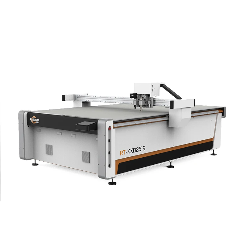
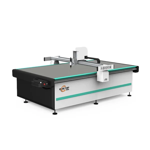
Per-Material Tool Head Engineering — every RT-D2516 / RT-S2516 ships with a tool head and vacuum zoning plan locked to the buyer’s actual foam density, composite layup or flexible sheet, not a generic default.
Technical Specifications
| Parameter | Value |
|---|---|
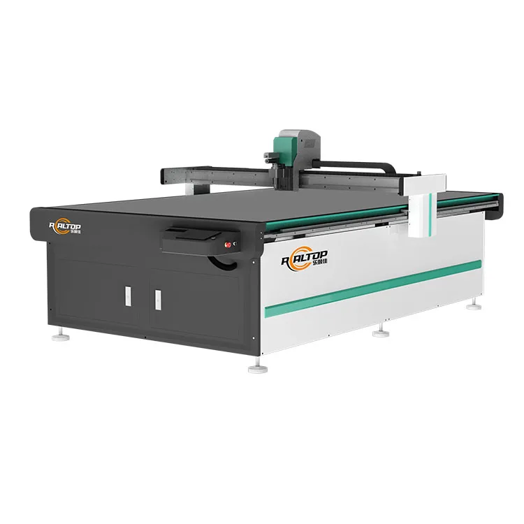
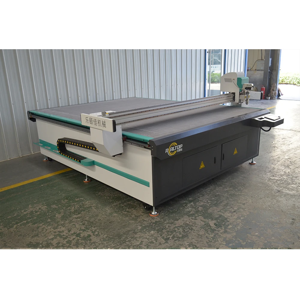
| Product Type | CNC Oscillating Knife Foam Insert Digital Cutting Machine |
| Model | RT-D2516 / RT-S2516 |
| Working Area | 1600 × 2500 mm |
| Overall Dimensions (L × W × H) | 3450 × 2300 × 1250 mm |
| Rated Power | 9 kW |
| Voltage | 380V ±10% (customizable per market) |
| Transmission System | Digital servo motor (Delta or Panasonic, IP67), linear guide, synchronous belt, ball screw; Taiwan Hiwin rail |
| Vacuum Pump | 7.5 kW, aviation aluminum shell with built-in silencer sponge |
| Vacuum Table | Magnesium-aluminum alloy, fluorocarbon PVDF powder spraying, anodic oxidation, hard oxidation treatment |
| Tool Head Options | Swiss imported knife (vibration full cutting, vibration half cutting, cursor location); oscillating knife, pneumatic knife, high-power vibrating knife, circular knife, V-cutting knife, drag knife, creasing wheel, dotted line knife, punching, brush |
| Visual Positioning | Small CCD camera mark-point positioning, panoramic camera recognition, projection positioning |
| Translational Velocity | 800–2000 mm/s |
| Cutting Speed | 200–800 mm/s (basis not stated in source — confirm with material, thickness and tool head) |
| Cutting Thickness | ≤100 mm (varies with material) |
| Repeated Accuracy | ≤0.1 mm |
| Instruction System | HP-GL compatible format |
| Safety Devices | Infrared induction blocking, anti-collision sensors on both sides of beam, emergency stop button |
| Working Table | Flat vacuum adsorption table; optional auto feeding with Germany imported conveyor belt |
| Machine Frame | Thick-walled seamless steel structure, high-temperature tempering, CNC machining center finished |
| Key Features | Multi-tool head interchange, CCD contour recognition, vacuum zoning, IP67 servo protection |
| Certification | CE declaration (where applicable) |
| Warranty | One year free warranty (domestic and abroad) |
Application Suitability
| Application | Material or Output |
|---|---|
| Foam insert cutting for protective packaging | EVA, EPE, PU foam, cross-linked polyethylene up to 100 mm |
| Composite gasket and seal fabrication | Carbon fiber prepreg, fiberglass, aramid, rubber sheet |
| Automotive interior trim production | Sponge composite leather, PVC, soft glass, silicone |
| Footwear and leather goods manufacturing | Natural leather, synthetic leather, textile laminates |
| Garment pattern sampling and short-run cutting | Woven fabric, non-woven, technical textiles |
| Carton and packaging sample making | Corrugated board, grey board, folding carton stock |
Why "200–800 mm/s" Means Nothing Without Your Material on the Table
A cutting speed range is only valid when tied to a specific foam density, composite thickness and tool head — everything else is marketing.
I have watched buyers sign off on a CNC oscillating knife cutting machine specifications sheet that promised 800 mm/s, only to discover on their factory floor that their 60 mm EVA foam insert required the head to slow to a fraction of that to avoid delamination and ragged edges. The speed number on the brochure was measured on thin vinyl with a drag knife — a completely different setup. Once the wrong tool head meets a dense composite or closed-cell foam, the blade chatters, the vacuum hold-down loses grip on small offcuts, and the operator spends more time re-cutting scrap than running production [NEED_CITE: oscillating knife cutting speed validation by material density and thickness].
Matching the Knife Type to the Composite Layup
The RT-D2516 / RT-S2516 carries a full tool head menu — Swiss imported vibrating blade, pneumatic knife, high-power oscillating knife, drag knife, V-cutting knife, creasing wheel, and punching tool — and the correct choice depends entirely on the material structure. A carbon fiber prepreg with directional fibers and variable resin content demands a different oscillation frequency and blade geometry than a closed-cell polyethylene foam. This is where a buyer’s CNC oscillating knife cutting machine specifications must be written around the actual stock, not a catalog default.
Vacuum Zoning That Holds Small Offcuts Without Crushing the Sheet
The magnesium-aluminum alloy table with PVDF fluorocarbon coating and hard oxidation treatment is divided into independently controlled vacuum zones. For nested gasket patterns with small internal cutouts, selective zoning keeps the part locked flat while the surrounding material remains easy to strip. The 7.5 kW pump with aviation aluminum shell and integrated silencer sponge runs at a noise level that does not drown out the operator’s ability to hear blade chatter — a practical indicator that something is wrong with the cut [NEED_CITE: vacuum table zoning standards for CNC flatbed digital cutting].
What the Frame and Motion System Actually Mean for Repeatability
The thick-walled seamless steel frame goes through high-temperature tempering and is finished on a CNC machining center, which removes residual stress before the linear guides and ball screws are mounted. Paired with IP67-rated Delta or Panasonic servo motors on Taiwan Hiwin rails, the system holds ≤0.1 mm repeatability across the full 1600 × 2500 mm working area. In practice, this means a foam insert cut at one corner of the table matches the same part cut at the opposite corner — critical when inserts must press-fit into molded cases with tight tolerances. The cutting speed of 200–800 mm/s is achievable within this accuracy envelope, but the exact throughput depends on material behavior under the selected tool head (basis to be confirmed with sample cutting).
The Cost of Skipping the Material Test
I once specified an oscillating knife for a carbon fiber prepreg job based on a successful trial with standard fiberglass. When production started, the resin content and fiber orientation in the actual prepreg caused the blade to deflect mid-cut, producing frayed edges that failed the customer’s visual inspection. Nearly half the first batch was scrapped before we re-ran the tool head selection with the real material. That single oversight cost more in wasted stock and downtime than a proper sample cutting exercise would have taken [NEED_CITE: composite prepreg cutting failure modes by resin content and fiber direction].
What Happens When Configuration Is Left to Chance
A buyer who accepts a default tool head without verifying it against their specific foam density or composite layup will see ragged edges on dense materials, crushed cells on soft foams, and small parts lifting off the table mid-cut because the vacuum zoning was never matched to the nesting pattern. CCD contour recognition may be listed on the spec sheet, but if the camera has not been calibrated on the buyer’s actual printed registration marks at production speed, the system will drift and produce off-contour cuts that cannot be reworked.
Why Buyers Source This Build From REALTOP
The in-house design team covers both oscillating knife and drag knife technologies under one roof, so the cutting method is matched to the material rather than forced into a single head type. Tool head and vacuum table zoning are specified per material sample before the order is confirmed. CCD camera positioning is validated on the buyer’s printed stock at target production speed, not just demonstrated on a clean test sheet. Voltage, plug standard, and control language are locked in before shipment to avoid on-site rewiring. Sample cutting on the buyer’s own foam, prepreg or leather is standard procedure, producing a documented edge quality and speed baseline that travels with the machine.
Documentation & Verification
- Machine specification sheet listing each configured tool head and its designated material
- Electrical schematic with confirmed voltage, frequency, and plug standard for destination market
- Sample cutting report on buyer’s foam density or composite layup with edge quality photographs
- Tool head and vacuum table zoning configuration list matched to buyer’s part nesting geometry
- HP-GL file format compatibility note confirming integration with buyer’s existing CAD workflow
- Factory test record documenting repeatability measurement across the 1600 × 2500 mm table before dispatch
Installation, Commissioning & Support
- 3450 × 2300 mm footprint requires level concrete floor with clearance for material loading on all sides
- 9 kW rated power plus 7.5 kW vacuum pump require dedicated 380V circuit with confirmed amperage
- Machine ships fully assembled; rigging plan must account for 2300 mm width through workshop doors
- First-run commissioning includes vacuum zone mapping and tool head calibration on buyer’s material
- Operator training covers tool head changeover, CCD mark-point setup, and HP-GL file import workflow
- Spare parts list includes Swiss knife blades, vacuum seals, and servo motor belts for first-year coverage
What We Need to Quote Accurately
Send us the material type, thickness range, and maximum sheet size you will be cutting most often. Include your local voltage and frequency standard, preferred control language, and whether your workflow relies on specific CAD file formats beyond HP-GL. If you are cutting printed contours, provide a sample of the actual printed stock so we can validate CCD mark-point tracking at production speed before the machine is built.
Frequently Asked Questions
Q: How is cutting speed verified and what material is it based on?
A: The stated 200–800 mm/s range depends entirely on material density, thickness, and tool head selection. We run a sample cutting test on your actual foam, composite, or leather before the order is finalized, documenting the achievable speed with the configured tool head and vacuum zoning so you have a verified throughput baseline rather than a catalog estimate.
Q: Which tool head should I choose for my foam or composite?
A: Head selection depends on material structure and thickness up to 100 mm. Dense closed-cell foam typically requires a high-power oscillating knife, while directional composites like carbon fiber prepreg need a specific blade geometry and oscillation frequency. We test multiple heads on your sample stock and document which one delivers the required edge quality.
Q: How is CCD contour recognition validated at production speed?
A: We run your actual printed material through the small CCD mark-point and panoramic camera systems at target cutting speed before shipment. This confirms the camera tracks registration marks accurately without drift, addressing the common failure where contour recognition works on a test sheet but loses tracking during real production runs.
Q: Is the vacuum table zoning sufficient for small nested parts?
A: The magnesium-aluminum table is divided into selectable zones configured around your nesting pattern. We map vacuum hold-down against your smallest part geometry during sample cutting to confirm that offcuts stay flat and do not lift into the blade path, which would otherwise cause edge damage and unplanned stops.
Q: What voltage, plug, and language options are available?
A: The standard configuration is 380V ±10%, but voltage, plug type, and control panel language are confirmed before production to match your facility. We document the final electrical specification in the schematic so there are no surprises when the machine arrives on your floor.


商品评价
Clear filtersThere are no reviews yet.