

Fast Shipping
Carrier information

20k products
Payment methods

24/7 Support
Unlimited help desk

2-day Delivery
Track or off orders
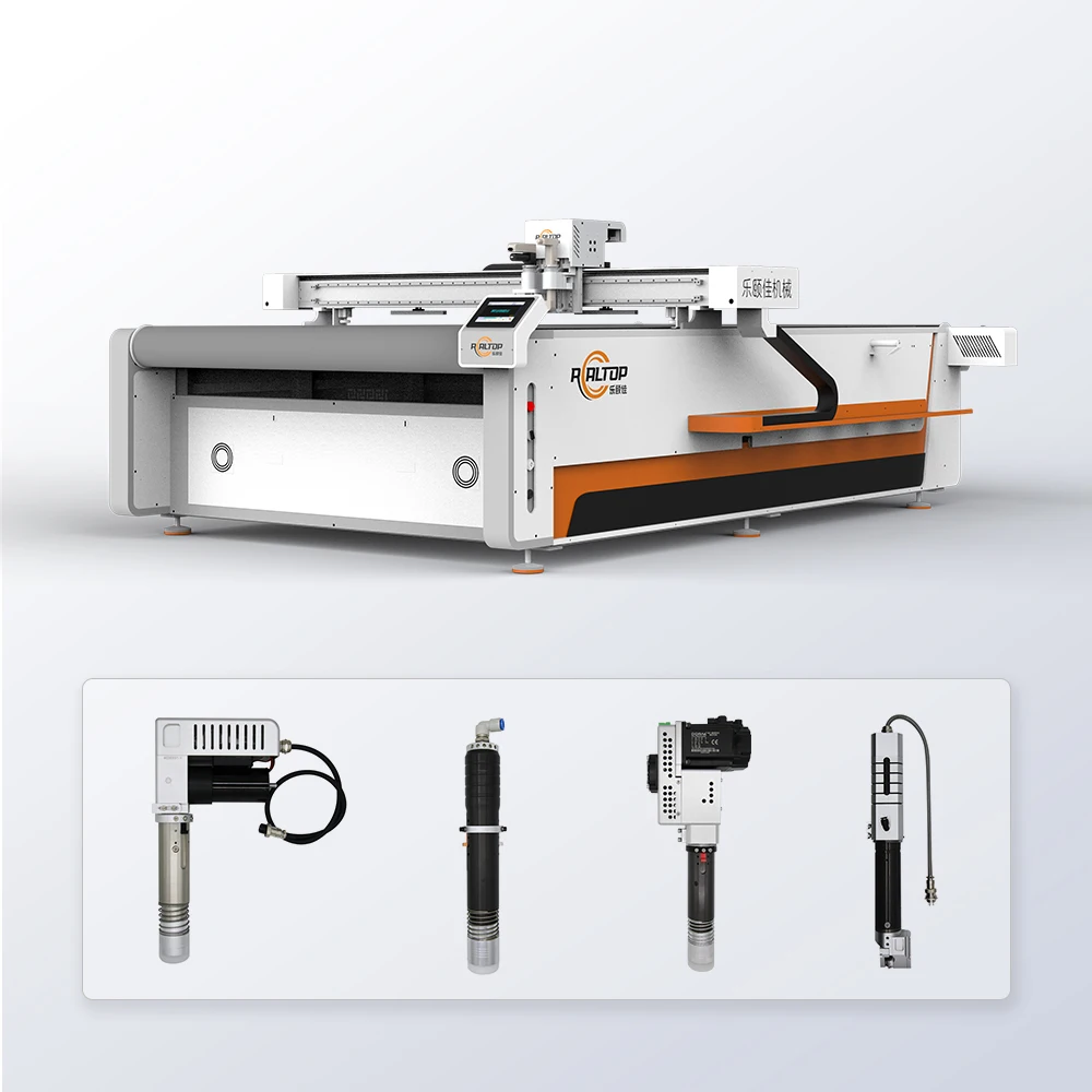
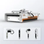
Tool Head Matrix — Swiss oscillating, drag, circular, V-cutting, creasing and punching heads configured against your specific material stack rather than forced into a single cutting method.
Technical Specifications
| Parameter | Value |
|---|---|
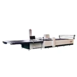
| Model | RT-D2516 / RT-S2516 |
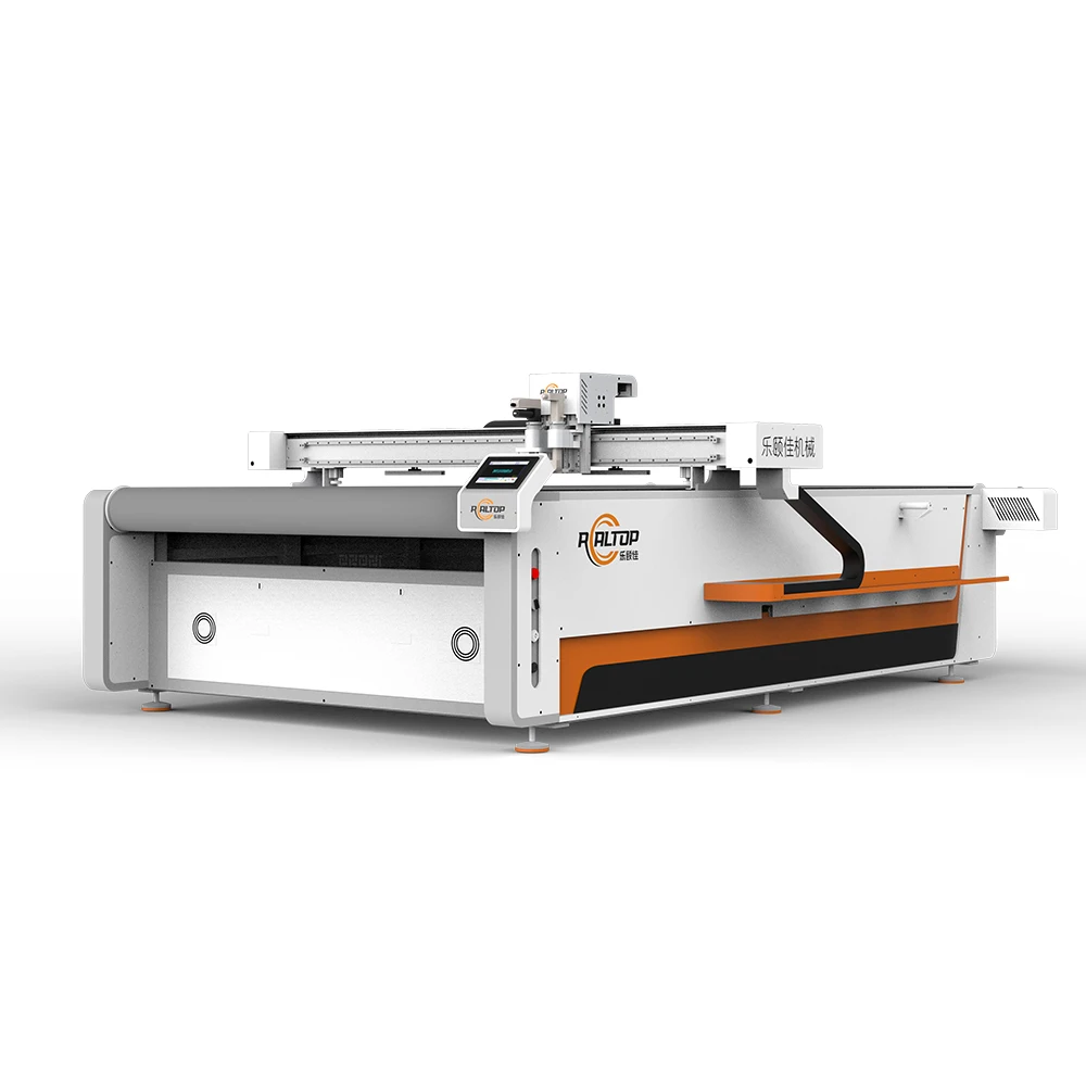
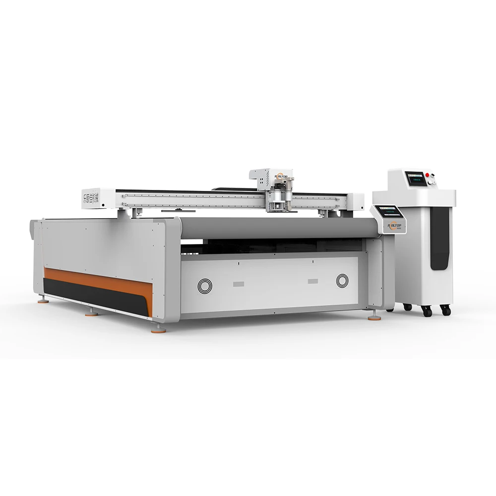
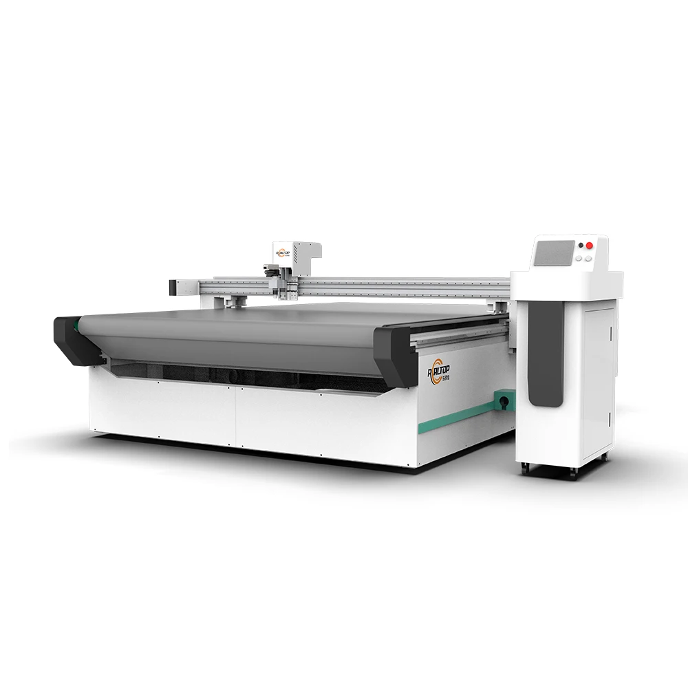
| Product Type | CNC Oscillating Knife Cutting Machine |
| Working Area | 1600 × 2500 mm |
| Machine Size (L × W × H) | 3450 × 2300 × 1250 mm |
| Rated Power | 9 kW |
| Voltage | 380V ± 10% (frequency to be confirmed per destination market) |
| Control System | CNC touch screen panel, multi-language (EN/RU/IT/ZH, others customizable) |
| Transmission | Digital servo motor (Delta or Panasonic, IP67), Taiwan Hiwin linear guide, synchronous belt, ball screw |
| Translational Velocity | 800 – 2000 mm/s |
| Cutting Speed | 200 – 800 mm/s (basis not stated in source — confirm with material and thickness) |
| Cutting Thickness | Up to 100 mm (varies with material density and tool head) |
| Repeatability | ≤ 0.1 mm |
| Vacuum Table | Magnesium-aluminum alloy, PVDF fluorocarbon powder spray, anodic and hard oxidation; 7.5 kW integrated pump with silencer |
| Tool Head Options | Swiss oscillating knife, pneumatic knife, high-power vibrating knife, circular knife, V-cutting, drag knife, creasing wheel, dotted line, punching, brush |
| Visual Positioning | Small CCD mark-point, panoramic camera recognition, projection positioning |
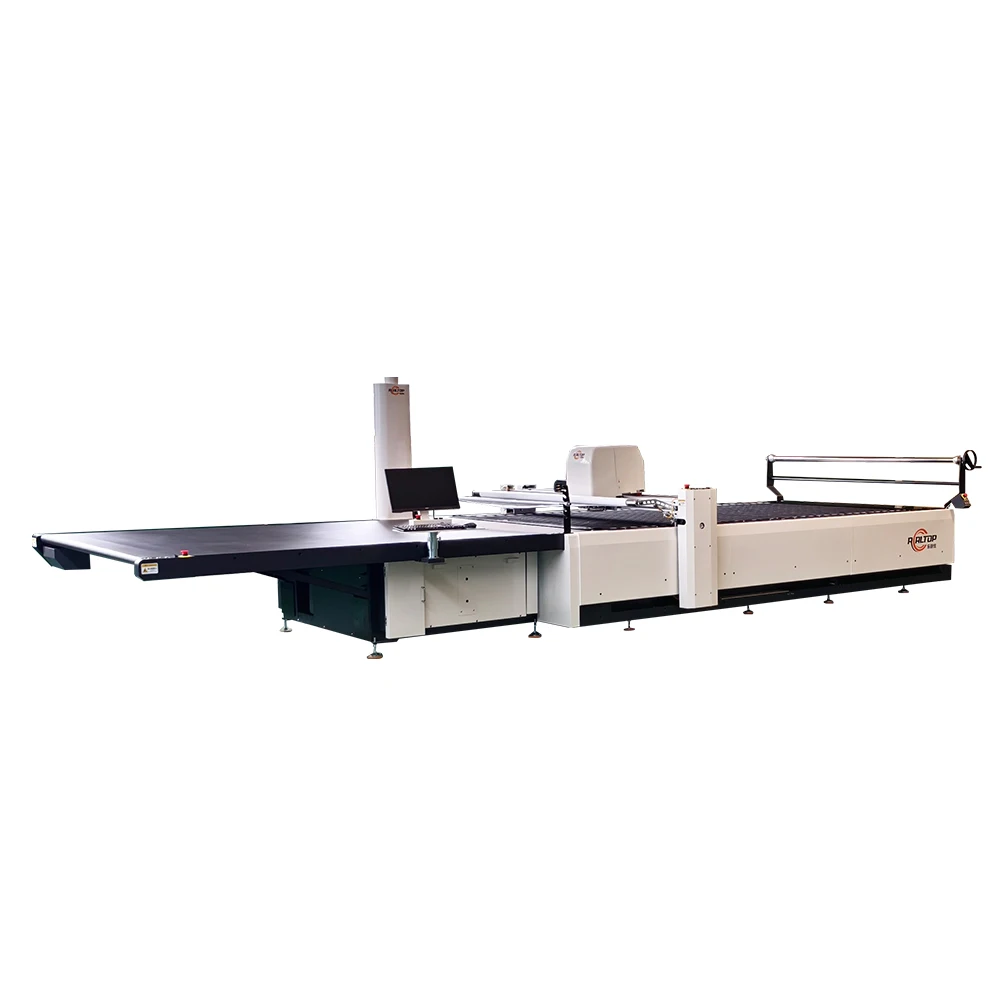
| Work Table Options | Flat table or auto-feeding conveyor (German belt) |
| Safety | Infrared induction block, dual-side anti-collision sensors, emergency stop with in-situ resume |
| File Compatibility | PLT, DXF, AI; HP-GL instruction format; auto nesting and typesetting |
Application Suitability
| Application | Material or Output |
|---|---|
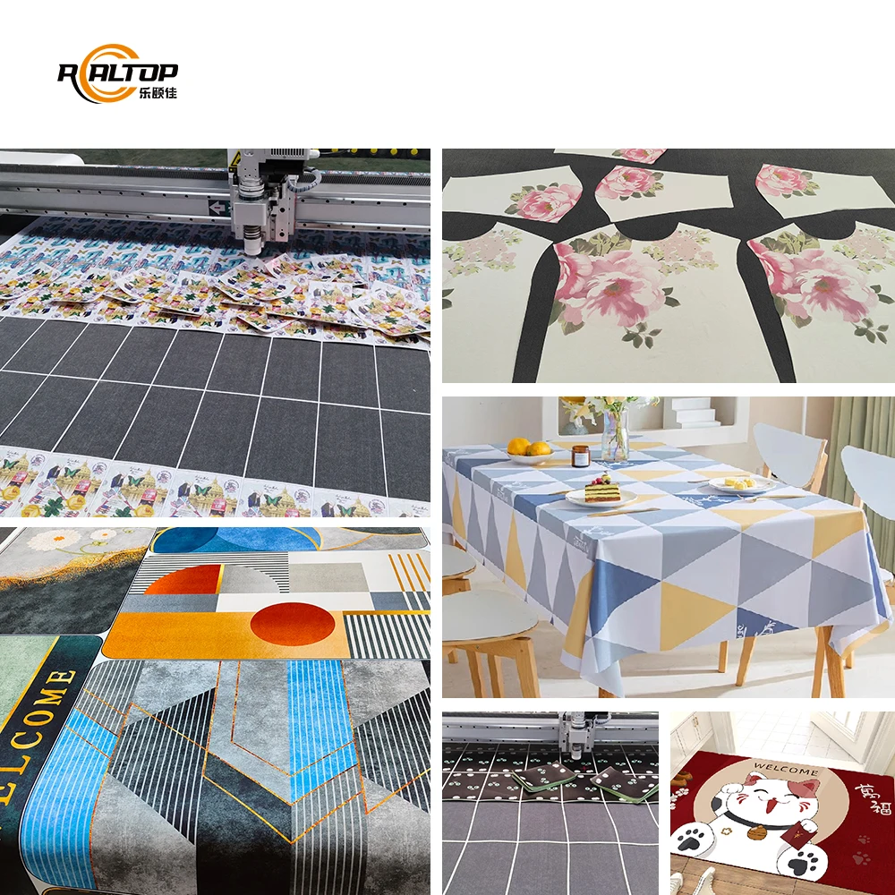
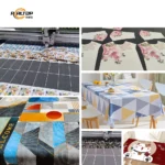
| Automotive interior trimming | Car mats, window tint film, multi-layer composite laminates |
| Garment and footwear production | Clothing cloth, shoe uppers, luggage material, fur, sofa fabric |
| Signage and advertising | Vinyl, sticker sheets, reflective film, self-adhesive board |
| Packaging sample making | Corrugated cardboard, carton stock, plastic box substrates |
| Gasket and sealing fabrication | Rubber, PU, EVA, XPE, PTFE, ETFE, PP, PE, PTFE |
| Foam and composite processing | Sponge, carpet, PVC foam, multi-layer technical textiles |
What the Quoted Cutting Speed Actually Means on Your Shop Floor
The headline speed only matters once you confirm it against your exact material stack and the tool head required to cut it cleanly.
I have seen fabricators quote a machine based on translational velocity alone, then discover that cutting multi-layer car mat composites at that rate produces crushed foam cores and delaminated face fabrics. The 200–800 mm/s range listed for CNC oscillating knife cutting machine specifications is a translational envelope, not a guaranteed throughput figure — real cutting speed depends on whether you are slicing a single layer of window tint film or pushing through 30 mm of dense EVA foam with a high-power vibrating head. [NEED_CITE: material density and tool head selection impact on achievable cutting speed]
Matching Tool Head Geometry to Material Behaviour
The Swiss oscillating knife handles full and half cutting on most single-layer and multi-layer fabrics, but the moment you switch to dense gasket rubber or closed-cell XPE foam, the standard head may leave ragged edges or require excessive downward force. The pneumatic knife and high-power vibrating knife options exist because oscillation frequency and stroke length must match material cell structure. Selecting the wrong head is the most common reason buyers see edge compression on foam or frayed edges on technical textiles.
Vacuum Zoning Determines Whether Small Parts Stay Flat
The magnesium-aluminum vacuum table with PVDF fluorocarbon coating provides a durable, low-friction surface, but the real question is how the table is zoned. A 1600 × 2500 mm bed with undifferentiated suction will lose hold-down pressure on parts smaller than a defined minimum area — small gaskets, signage letters, or garment pattern pieces can lift during the final cut pass, ruining the nest and the blade. [NEED_CITE: vacuum table zoning requirements for small-part CNC knife cutting]
Reading the Specifications Against Your Production Reality
The ≤ 0.1 mm repeatability figure is achievable because of the IP67-rated servo motors, Hiwin linear rails, and ball screw drive — but repeatability only matters if the machine maintains it across an eight-hour shift with varying ambient temperature and dust load. The 9 kW rated power accounts for the spindle servo, vacuum pump (7.5 kW alone), and control system simultaneously. If your facility runs on a shared circuit with other heavy equipment, voltage sag under load will affect servo response before it trips a breaker. [NEED_CITE: voltage stability requirements for CNC servo-driven cutting equipment]
The Cost of Specifying on Working Area Alone
Choosing a machine based solely on bed size and then discovering it cannot hold small parts flat or push a blade through your material thickness is a downtime event, not a negotiation point. Three months into production, a car mat line I visited was completely stalled because the oscillating head could not penetrate the multi-layer composite at acceptable speed — the buyer had skipped the tool head conversation and gone with the default configuration. Reconfiguring the head, re-running sample cuts, and recalibrating the vacuum zones took the line offline for over a week. [NEED_CITE: production downtime costs from misconfigured CNC cutting equipment]
Why Sourcing This Configuration Here
The design team covers both knife and laser cutting technologies in-house, which means the recommendation starts with your material rather than with whichever machine is on the showroom floor. Tool head and vacuum table configurations are specified per material type, thickness, and daily volume before the order is placed — not assumed from a catalogue default. CCD contour recognition options are tested with your actual printed artwork at target production speed before shipment. Sample cutting on your own material, documented in a report with edge quality photographs, happens before you commit. Voltage, control language, and file format compatibility are confirmed in writing before production begins.
Documentation & Verification
- Machine specification sheet listing confirmed tool head and vacuum zone layout
- Electrical schematic with voltage and frequency matched to your facility supply
- Sample cutting report on your material with edge quality and speed documentation
- Tool head and table configuration list signed off before production release
- Software licence and file format compatibility note for your nesting workflow
- Factory test record with repeatability measurement across full working area
Installation, Commissioning & Support
- 3450 × 2300 mm footprint requires level floor with clearance for material loading on three sides
- 9 kW total draw and 380V supply need a dedicated circuit with confirmed frequency
- Fully assembled shipping to be confirmed — verify access dimensions for workshop doors
- First-run parameter setting covers servo tuning, vacuum zone mapping, and CCD calibration
- Operator training on tool head changeover, blade replacement, and nesting software workflow
- Spare parts list includes oscillating knife blades, vacuum seals, and drive belts
What We Need to Quote You Accurately
Send the material type, thickness, and maximum sheet size you plan to cut, along with your target daily volume and whether your artwork requires CCD contour tracking. Confirm your facility voltage and frequency, the control language your operators need, and which file formats your current design software exports. If you have existing upstream printing or downstream sewing equipment, note the feed dimensions so the auto-feeding conveyor option can be evaluated against your line.
Frequently Asked Questions
Q: How do I match the tool head to my material and thickness?
A: Each head — oscillating, pneumatic, circular, drag, V-cutting — suits a different material cell structure and thickness range. The correct selection is based on a sample cut using your actual material, documented with edge quality photographs and the speed achieved, so the configuration is locked before the machine enters production.
Q: Will the CCD system track my printed marks at full production speed?
A: Small CCD mark-point, panoramic camera, and projection positioning options are all available, but mark tracking reliability depends on print contrast, mark size, and belt speed. The test must be run with your actual artwork at your target throughput, not demonstrated on a supplier’s sample sheet.
Q: How is vacuum table zoning handled for small parts?
A: The 1600 × 2500 mm magnesium-aluminum table can be zoned to maintain suction on parts below a minimum area threshold. The zoning layout must be specified against your typical nest pattern before build, especially if your production includes small gaskets, signage letters, or garment components.
Q: What cutting speed and thickness can I expect on my specific material?
A: The listed 200–800 mm/s range and up to 100 mm thickness are machine envelopes, not guaranteed outputs. Your actual figures depend on material density, tool head selection, and layer count — confirmed only through a sample cut report on your own stock before order commitment.
Q: Which file formats and nesting workflows are supported?
A: The system imports PLT, DXF, and AI files and uses HP-GL compatible instructions with built-in auto nesting. If your current workflow relies on a different format or third-party nesting software, compatibility must be verified against your files before the machine ships.


商品评价
Clear filtersThere are no reviews yet.