



Fast Shipping
Carrier information

20k products
Payment methods

24/7 Support
Unlimited help desk

2-day Delivery
Track or off orders
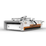
Tool Head and Vacuum Table Configuration Specified Per Fabric Type — The 1625 CNC oscillating knife cloth cutter is matched to your material thickness and production volume, from single-ply wovens to 50 mm multi-layer layups, with tool head and adsorption zoning confirmed before the order is placed.
Technical Specifications
| Parameter | Value |
|---|---|
| Model | 1625 |
| Product Type | CNC Oscillating Knife Cloth Cutter |
| Working Area | 1600 × 2500 mm |
| Machine Size | 3300 × 2100 × 1350 mm |
| Cutting Speed | 0 – 2000 mm/s |
| Textile Cutting Speed | 1200 – 2000 mm/s (basis not stated in source) |
| Multi-layer Cutting Capacity | 30 – 50 mm thickness per pass (basis not stated in source) |
| Cutting Thickness | ≤ 30 mm (basis to be confirmed by material type) |
| Positioning Accuracy | ± 0.1 mm |
| Tool Head Options | Oscillating knife, Driven rotary knife, Creasing wheel, Kiss cutting tool, Pneumatic knife, Milling tool, V-groove knife |
| Vacuum Table | Aluminum bellows vacuum table with full-surface adsorption |
| Vacuum Pump Power | 9 kW |
| Servo Motor Options | Panasonic, Delta, Dorna |
| Control System | PLC control panel with intuitive interface |
| File Format Compatibility | PLT, DXF, AI, PDF |
| Voltage Options | 110V, 220V, 380V |
| Software Language Options | English, Russian, Italian, Chinese (custom languages available) |
| Safety Devices | Infrared sensor device, Emergency stop device |
| Standards | CE declaration where applicable |
Application Suitability
| Application | Material or Output |
|---|---|
| Apparel Manufacturing | Suits, knitwear, lace, and complex woven or knit fabrics |
| Automotive Interiors | Seat fabrics, carpets, PVC mats |
| Home Textiles | Sofa fabrics, curtains, rugs |
| Composite Material Processing | Carbon fiber prepreg, aramid, specialty materials |
| Flexible Non-Metals | Cardboard, carton, mats, EVA, leather, acrylic, foam, PTFE, rubber |
Why the Vacuum Table Question Should Come Before the Price
A 9 kW vacuum pump means nothing if the zoning does not match your cutting layout.
When a buyer specifies a cloth CNC cutting machine based only on the working area, the first problem that surfaces on the factory floor is material movement. Small pattern pieces on multi-layer stretch fabric tend to lift the moment the oscillating knife releases pressure, and if the vacuum zones are not mapped to the actual nesting arrangement, the blade drags the material and ruins the entire lay. I have seen this exact failure on an automotive seat cover line where a single-zone table was paired with a high-density nesting layout, resulting in a batch of ruined covers before the cause was identified [NEED_CITE: vacuum table zoning and material hold-down in textile cutting operations].
Matching the Knife Type to the Fabric Structure
The 1625 platform supports a range of tool heads — oscillating knife, driven rotary knife, kiss cutting tool, and creasing wheel among them — and selecting the correct one depends entirely on the fabric construction and the number of layers in the lay. A driven rotary knife works well for single-ply woven material where a continuous cut prevents fraying, while an oscillating knife is typically the choice for multi-layer stacks because the vertical reciprocating motion keeps the blade from deflecting through the lay. Specifying the CNC oscillating knife cloth cutter with the correct tool head eliminates secondary trimming and protects edge integrity across the entire production run.
Aluminum Bellows Table and Adsorption Zoning
The aluminum bellows vacuum table on the 1625 is designed for full-surface adsorption, but the critical configuration decision is how the table surface is divided into independent zones. For garment factories cutting a mix of large panels and small collar or cuff pieces, the zoning must be set so that suction remains active under the small parts even after the surrounding fabric has been cut away. This zoning layout should be confirmed against the buyer’s actual nesting patterns before the table is built, not adjusted after delivery when production losses have already occurred [NEED_CITE: aluminum vacuum table construction and zone configuration for textile cutting].
Reading the Specification Sheet Against Your Material
The positioning accuracy of ± 0.1 mm matters most when cutting pattern pieces that will be sewn together with tight seam allowances — any drift accumulates across a garment and shows up as misaligned panels at the sewing station. The stated cutting speed range of 0 – 2000 mm/s provides flexibility, but the usable speed on your production floor depends on the fabric density and the number of layers in the lay; a dense woven behaves very differently from a loose knit at the same traverse rate. The 9 kW vacuum pump must generate sufficient negative pressure across the entire 1600 × 2500 mm surface, and the servo motor selection — whether Panasonic, Delta, or Dorna — affects how smoothly the gantry decelerates at the end of each cut path, which directly influences corner accuracy on complex shapes.
The Cost of a Wrong Configuration Choice
Choosing a vacuum table without verifying zone layout against the buyer’s nesting plan leads to material shift mid-cut, and on multi-layer lays this means the bottom layers shift relative to the top, producing tapered edges that fail quality inspection. Selecting a tool head based on price rather than fabric construction results in crushed edges on foam-backed materials or pulled threads on delicate knits, creating waste that compounds across every shift. These configuration errors are only discovered once the machine is running production material, which is why the configuration list must be documented and agreed upon before manufacturing begins [NEED_CITE: material waste caused by incorrect cutting tool selection].
Why Buyers Source This Configuration Here
The tool head and table configuration is specified against the buyer’s actual fabric sample, not a generic material chart, so the cutting method is matched to the material rather than forced into one approach. CCD camera positioning is available for printed contour work where the cut path must follow a registered mark rather than a fixed coordinate. Software compatibility is verified before the order, confirming that the buyer’s existing DXF, AI, PLT, or PDF nesting files import and run without format conversion. Voltage, plug type, and control language are confirmed to match the destination factory’s electrical infrastructure and operator requirements. Sample cutting is performed on the buyer’s own material before commitment, generating a report that documents edge quality, layer capacity, and achievable speed under real conditions.
Documentation & Verification
- Machine specification sheet listing confirmed tool head and vacuum zone configuration
- Electrical schematic with voltage and frequency matched to destination market
- Sample cutting report produced on the buyer’s own fabric or composite material
- Software licence and file format compatibility note for existing nesting workflows
- Factory test record documenting positioning accuracy and cut quality before dispatch
- Spare parts list identifying wear items for the specified tool head configuration
Installation, Commissioning & Support
- Floor space allocation based on the 3300 × 2100 mm machine footprint plus operator clearance
- Dedicated electrical circuit sized for the 9 kW vacuum pump plus servo and control load
- Table leveling and vacuum zone calibration against the confirmed zoning layout
- PLC control panel setup with the confirmed operator language and file import test
- First-article cutting run on production material to verify edge quality and positioning accuracy
- Wear blade and tool head consumable schedule provided with initial spare parts set
Preparing Your Cutting Inquiry
To configure the 1625 correctly, provide the fabric type, the number of layers in a typical lay, the thickest material you plan to cut, and a sample nesting layout so the vacuum zoning can be planned around your actual part sizes. Include your local voltage and frequency, the preferred control language, and a set of production files in your native format so software compatibility can be verified before the order is finalized. If printed contour cutting is part of your workflow, share a sample printed sheet so CCD registration can be tested against your print quality.
Frequently Asked Questions
Q: How is cutting thickness verified for my specific fabric type and layer count?
A: A sample cutting test is run using your actual fabric in the exact lay configuration you plan to use in production. The test documents edge quality, layer separation, and achievable cutting speed, and the results are shared in a written report before you commit to the order.
Q: Which tool head is recommended for my material — oscillating knife vs rotary knife?
A: The choice depends on fabric construction and layer count. Oscillating knives generally suit multi-layer stacks, while rotary knives work well for single-ply wovens. Your material sample is cut with the candidate tool heads to confirm which produces the cleanest edge.
Q: How does vacuum table zoning handle small parts that tend to lift during cutting?
A: The aluminum bellows table is divided into zones configured against your actual nesting layout. This ensures suction remains active under small pieces even after surrounding material has been cut away, preventing lift and drag damage.
Q: Can the software import my existing DXF or AI nesting files?
A: The control system supports PLT, DXF, AI, and PDF formats. Your production files are imported and tested during the pre-order stage to confirm that geometry, layer assignments, and cut paths transfer without conversion errors.
Q: What voltage and control language options are available for my factory?
A: Voltage options include 110V, 220V, and 380V, and the PLC interface is available in English, Russian, Italian, Chinese, or a custom language. The exact combination is confirmed before shipment to match your site infrastructure.


商品评价
Clear filtersThere are no reviews yet.