




Fast Shipping
Carrier information

20k products
Payment methods

24/7 Support
Unlimited help desk

2-day Delivery
Track or off orders
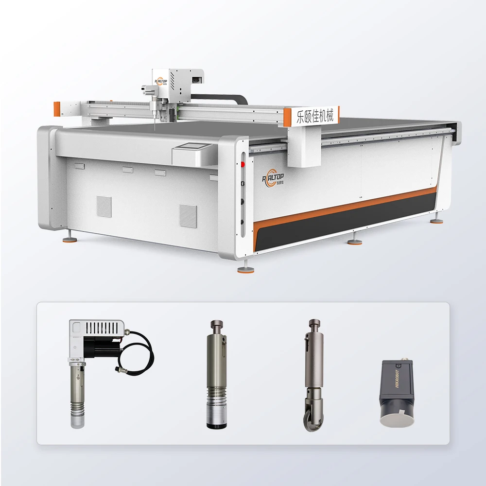
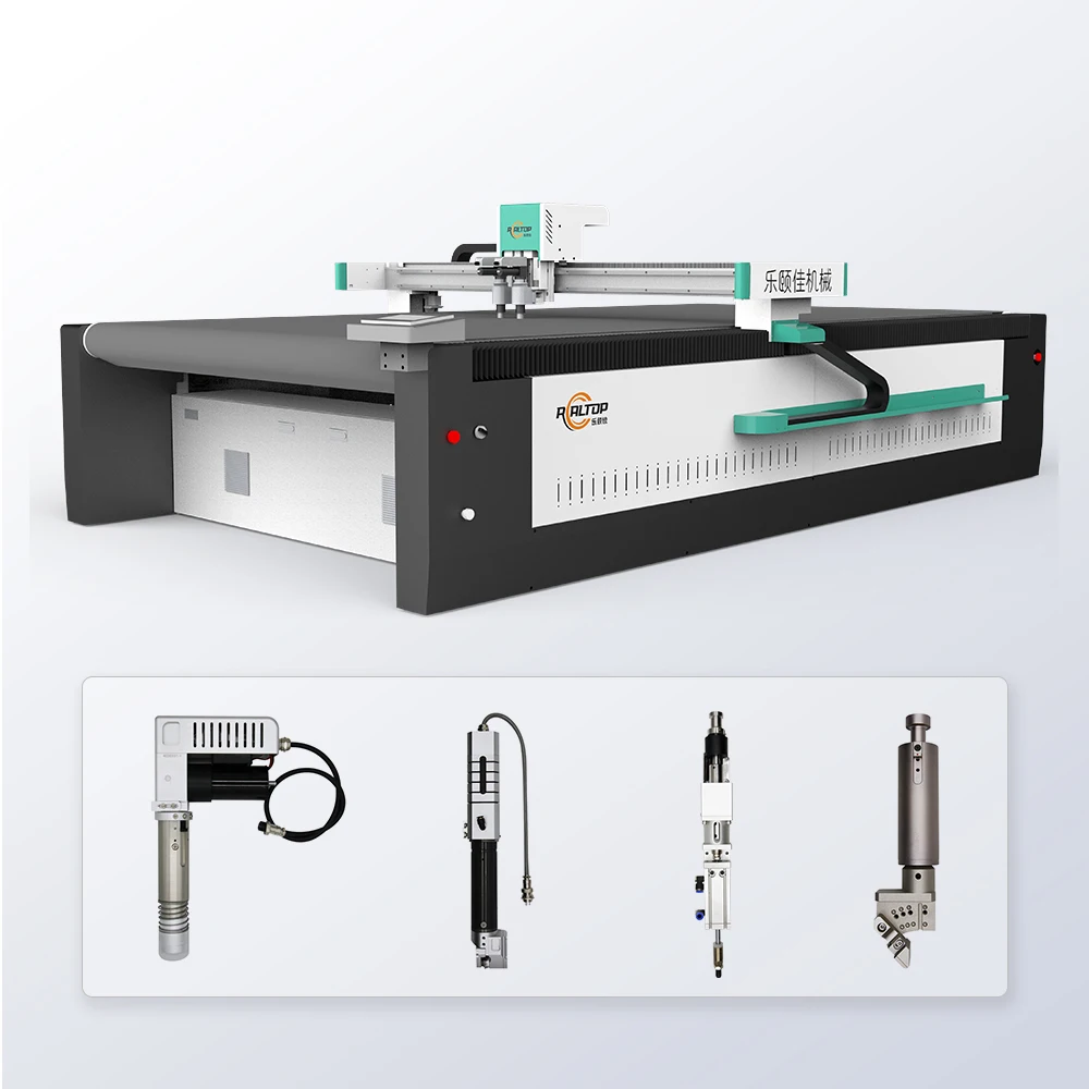
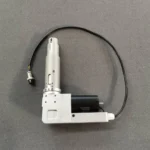
Material-Matched Tooling — The RT-D2516/RT-S2516 platform supports oscillating knife, drag knife, creasing wheel, punching and more, so the cutting method is chosen after sample testing on your actual stock rather than forced to a single blade type.
Technical Specifications
| Parameter | Value |
|---|---|
| Product Type | CNC Oscillating Knife Cutting Machine |
| Model | RT-D2516 / RT-S2516 |
| Working Area | 1600×2500 mm |
| Machine Size | 3450×2300×1250 mm |
| Rated Power | 9 kW |
| Voltage | 380V ±10% (frequency to be confirmed per market) |
| Control System | CNC, HP-GL compatible format |
| Translational Velocity | 800–1200 mm/s |
| Cutting Speed | 200–800 mm/s (varies with material type and thickness) |
| Cutting Thickness | ≤100 mm (material dependent) |
| Repeated Accuracy | ≤0.1 mm |
| Transmission System | Digital servo motor (Delta or Panasonic optional), Taiwan Hiwin linear guide, synchronous belt, ball screw |
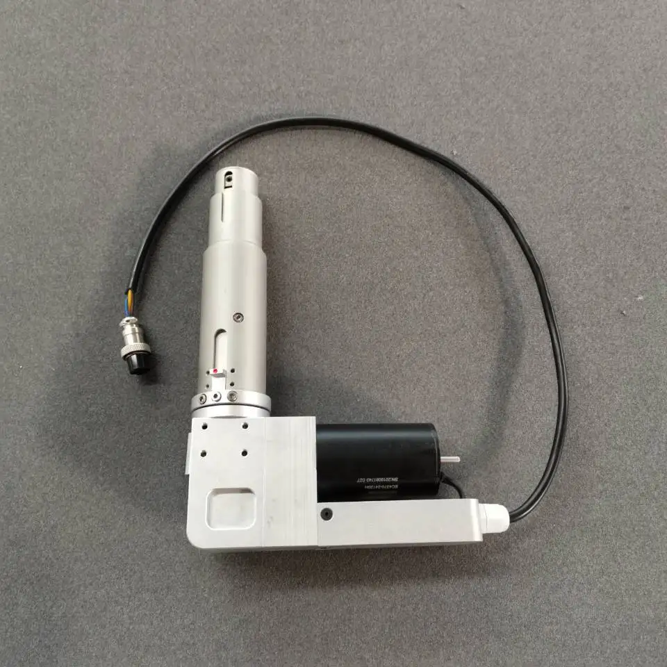
| Tool Head Options | Oscillating knife, pneumatic knife, high-power vibrating knife, circular knife, V-cutting knife, drag knife, creasing wheel, dotted line knife, punching, brush |
| Visual Positioning | Small CCD camera mark point positioning, panoramic camera recognition, projection positioning |
| Vacuum Table | Magnesium-aluminum alloy, PVDF fluorocarbon powder spraying, anodic oxidation, hard oxidation |
| Vacuum Pump | 7.5 kW, aviation aluminum shell, built-in silencer sponge |
| Safety System | Infrared induction blocking, anti-collision, emergency stop |
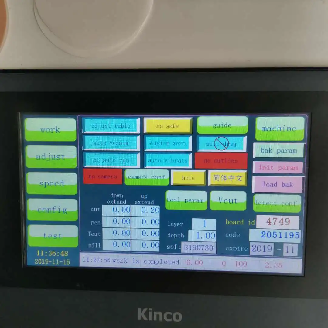
| Language Options | English, Russian, Italian, Chinese (custom languages available) |
| Assembly State | Fully assembled |
Application Suitability
| Application | Material or Output |
|---|---|
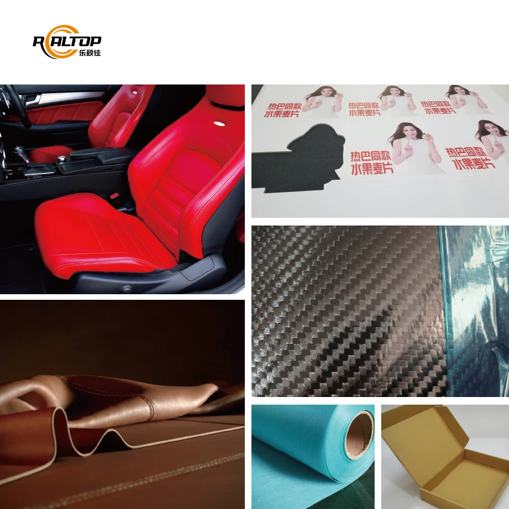
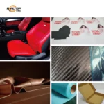
| Packaging and carton sample making | Corrugated cardboard, plastic box materials, film, sticker stock |
| Leather and footwear production | Natural leather, PU leather, shoe uppers, luggage materials |
| Textile and garment cutting | Multi-ply fabric, clothing cloth, technical textiles |
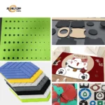
| Foam and gasket fabrication | Foam board, sponge, PU, EVA, XPE, PTFE, ETFE, composite sheets |
| Automotive interior trimming | Carpet, floor mat material, soft trim composites |
| Advertising and signage | PVC board, vinyl, printed contour media |
Why Cutting Quality Fails Before the First Sheet Is Finished
Specifying a CNC oscillating knife cutting machine on working area alone, then discovering the blade cannot handle your material thickness, is a failure pattern I have traced across multiple packaging and textile workshops. Edge raggedness and crushed foam almost always trace back to a tool head chosen without sample testing on the buyer’s actual stock.
In the Pearl River Delta packaging sample shops I serviced for years, operators would bring in corrugated board for trial cuts and then go back to cutting laminated grey board in daily production — the knife pressure, vibration frequency and blade angle all had to be reworked from scratch. That mismatch between trial material and real production stock is where most edge quality complaints originate [NEED_CITE: cutting tool selection by material density and thickness]. The specification sheet confirms what is possible; the sample cut on your own material confirms what actually happens.
Matching the Blade to the Stock, Not the Other Way Around
The multifunctional head on this CNC oscillating knife cutting machine accepts a full range of interchangeable tooling — Swiss imported oscillating knife for clean full cuts and kiss cuts in one cycle, creasing wheel for folding lines on corrugated board, drag knife for vinyl and sticker contour work, and punching tools for gasket holes. Each tool head is specified against your material type and daily volume before the order is locked, so the machine arrives configured for what you actually cut rather than what looked good in a catalogue photo.
Holding Small Parts Down Without Crushing Them
Vacuum table zoning is where many flatbed cutters fail on small packaging samples and gasket pieces. The magnesium-aluminum alloy table on the RT-D2516/RT-S2516 uses PVDF fluorocarbon coating with hard oxidation for flatness, paired with a 7.5 kW vacuum pump that maintains suction across defined zones. When small parts lift during cutting because adjacent zones are not isolated, the blade drags and the edge tears [NEED_CITE: vacuum hold-down requirements for small-part CNC knife cutting]. Zoning configuration should be matched to your smallest typical part size, not just your largest sheet.
Reading the Numbers That Matter on the Specification Sheet
The 9 kW rated power covers the combined draw of servo drives, vacuum pump and tool head motor — this matters when sizing your workshop electrical supply, especially since the 380V ±10% baseline needs frequency confirmation for your local grid. The cutting speed range of 200–800 mm/s is material-dependent; a dense 10 mm EVA foam will cut at the lower end while thin sticker film runs near the upper bound. Repeated accuracy at ≤0.1 mm is maintained through the Taiwan Hiwin linear guides and digital servo system, which is critical when nesting multiple gasket profiles or packaging samples on a single sheet where cumulative drift ruins yield. The HP-GL compatible control format must be verified against your existing nesting software workflow before the machine ships — discovering a file format mismatch on delivery day is a problem that belongs in the quotation stage.
The Cost of Skipping the Configuration Conversation
When a buyer confirms only the working area and accepts whatever tool head comes standard, the consequences show up within the first production week. Laminated grey board requires different knife pressure and vibration frequency than bare corrugated, and a blade set for one will chew through the other. CCD contour recognition that cannot track printed marks at production speed turns a promising packaging sample run into manual rework. Voltage and plug assumptions left unresolved before shipment lead to weeks of idle time while transformers are sourced locally [NEED_CITE: electrical supply mismatch costs in exported CNC equipment]. Every one of these failures traces back to a specification that was left generic when it should have been locked to a specific material and production context.
What the Builder Brings to the Table
The in-house design and production team covers both knife and laser cutting technologies, which means the recommendation on cutting method comes from a workshop that builds both systems rather than a sales desk pushing whichever model is in stock. Tool head and table configurations are specified per material and production volume, not quoted from a fixed options list. CCD camera positioning for printed contour work is tested against your actual print quality and mark size. Software compatibility with your existing nesting workflow is confirmed before the order enters production. Sample cutting on your own material is completed and documented before commitment, so edge quality and throughput are verified facts rather than catalogue promises.
Documentation & Verification
- Machine specification sheet listing confirmed tool head and vacuum zone configuration for your material
- Electrical schematic with voltage and frequency matched to your workshop supply before dispatch
- Sample cutting report on your own stock verifying edge quality and achievable cutting speed
- Factory test record documenting repeated accuracy across the 1600×2500 mm working area
- Software licence and file format compatibility note covering HP-GL import and nesting workflow
- Operation and maintenance manual in your confirmed language with spare parts list included
Installation, Commissioning & Support
- Fully assembled 3450×2300×1250 mm frame requires adequate workshop door clearance and level concrete flooring
- 9 kW rated power needs a dedicated 380V ±10% circuit with frequency confirmed to your local grid standard
- Factory-run vacuum pump and servo system tested at full load before dispatch with documentation provided
- First-run commissioning includes tool head pressure calibration against your specific material thickness range
- Operator training covers tool changeover between oscillating knife, creasing wheel and drag knife configurations
- Spare parts list includes wear items specific to your confirmed tool head selection for ongoing maintenance
What to Prepare Before Requesting a Quote
Share the exact material types, thicknesses and sheet sizes you run in daily production — not just the trial samples. Confirm your local voltage and frequency, your preferred control language, and the file format your current nesting software exports. If you can send a roll or stack of your actual stock for sample cutting, the tool head configuration and achievable cutting speed will be locked before the quotation is issued rather than guessed after delivery.
Frequently Asked Questions
Q: How do I choose the right tool head for my material?
A: The correct tool head depends on material type, density and thickness — oscillating knife for clean cuts on fabric and foam, creasing wheel for folding lines on corrugated board, drag knife for thin vinyl and stickers. We run sample cuts on your actual stock to confirm blade type, pressure and vibration frequency before the configuration is finalized.
Q: How does the vacuum table handle small packaging parts?
A: The magnesium-aluminum alloy table supports zone-based suction so that small parts maintain hold-down even when surrounding areas are cut away. Zone layout should be matched to your smallest typical part size during the configuration stage to prevent lift and edge tearing during high-speed cutting passes.
Q: Can the CCD camera track printed marks at production speed?
A: The system offers both small CCD mark point positioning and panoramic camera recognition. Tracking reliability depends on print contrast, mark size and cutting speed — we test against your actual printed material to confirm that contour recognition holds accuracy across the full 1600×2500 mm working area before shipment.
Q: What voltage and language options are confirmed before shipment?
A: The baseline is 380V ±10% with frequency confirmed to your local grid. Control language options include English, Russian, Italian and Chinese, with custom languages available. Plug type, electrical schematic and language are all locked during the quotation stage, not left to assumption.
Q: Can I send my own material for sample cutting first?
A: Yes — sample cutting on your actual stock is a standard step before order commitment. The report documents edge quality, achievable cutting speed and tool head performance on your specific material, so the final configuration is based on verified results rather than catalogue specifications.


商品评价
Clear filtersThere are no reviews yet.