

Fast Shipping
Carrier information

20k products
Payment methods

24/7 Support
Unlimited help desk

2-day Delivery
Track or off orders
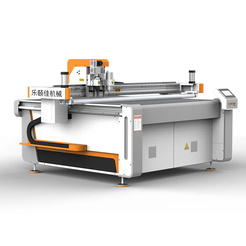
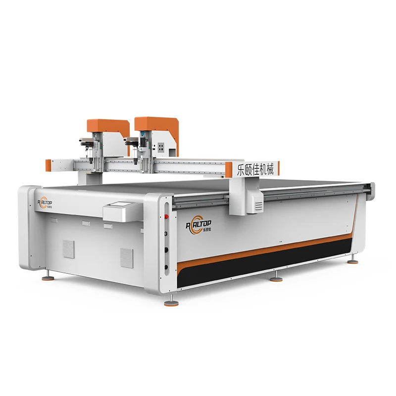
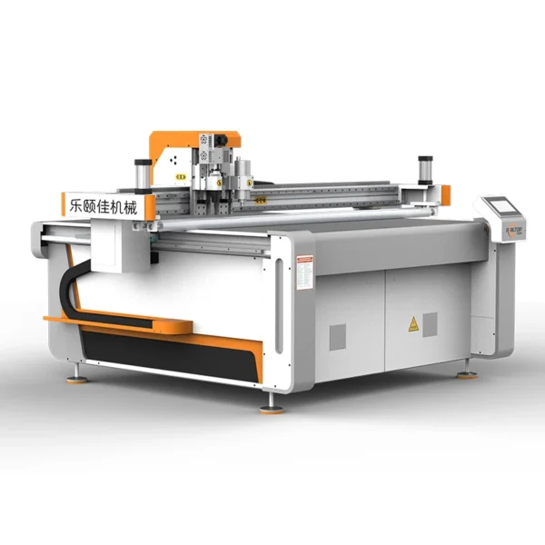
Oscillating Knife and Drag Knife Tool Heads — Each head is specified for the composite thickness and edge requirement rather than forcing a single blade type through every material, tested on the buyer’s own stock before shipment.
Technical Specifications
| Parameter | Value |
|---|---|
| Model | RT-D2516/RT-S2516 |
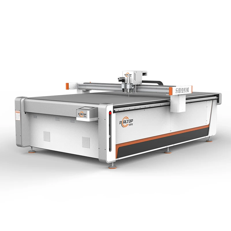
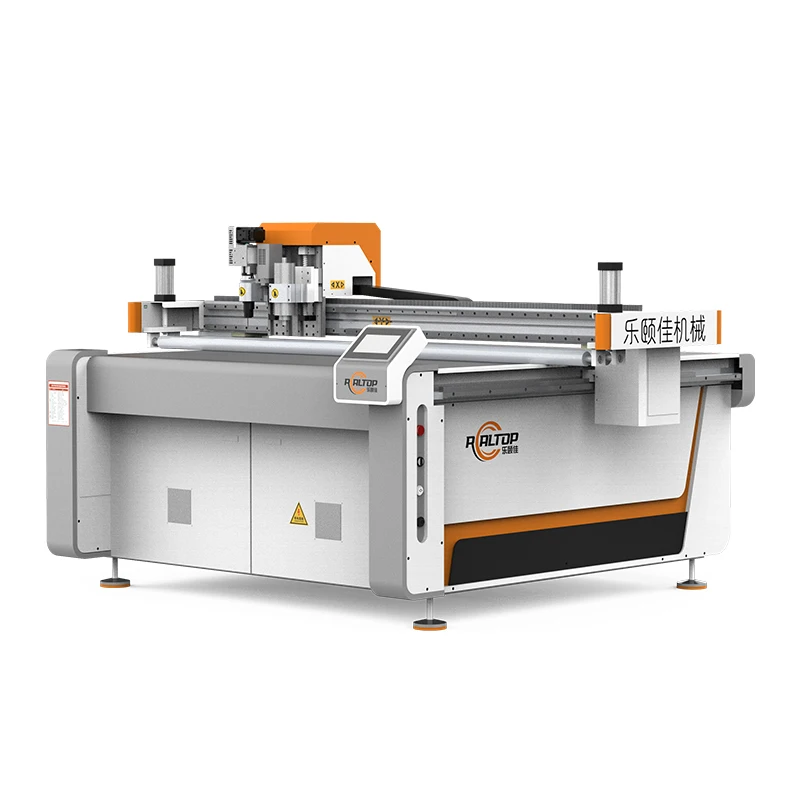
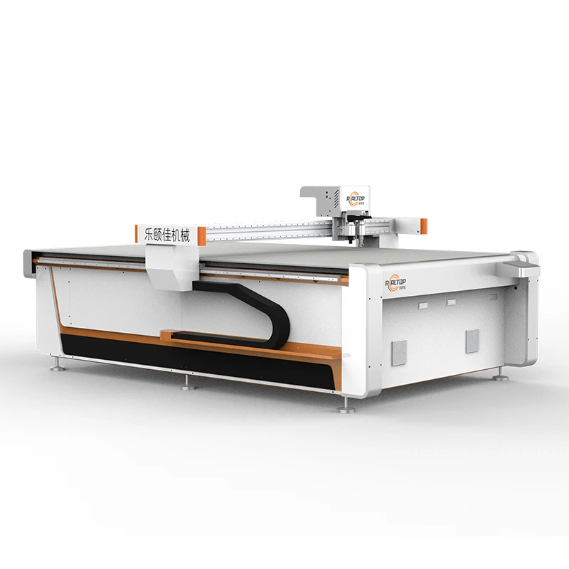
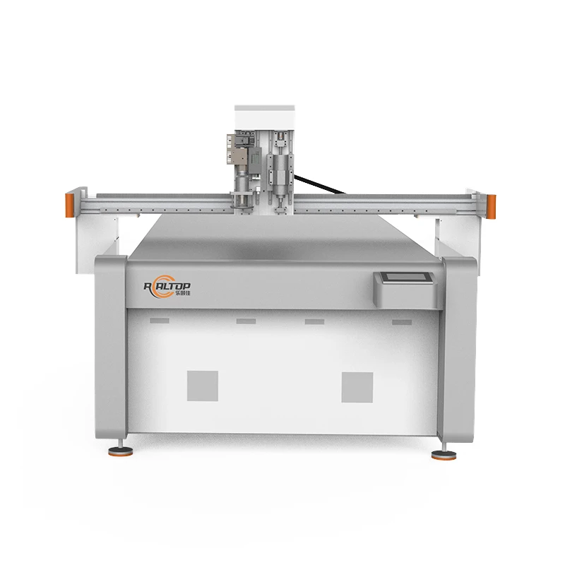
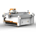
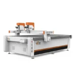
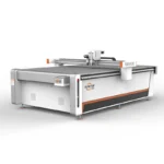
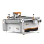
| Product Type | CNC Oscillating Knife Cutting Machine |
| Working Area | 1600 × 2500 mm |
| Machine Size | 3450 × 2300 × 1250 mm |
| Rated Power | 9 kW |
| Vacuum Pump | 7.5 kW |
| Translational Velocity | 800–2000 mm/s |
| Cutting Speed | 200–800 mm/s (basis not stated in source — confirm block format / material / thickness) |
| Repeated Accuracy | ≤0.1 mm |
| Transmission System | Digital servo motor, linear guide, synchronous belt, ball screw |
| Servo Motor | Delta (optional Panasonic) |
| Rail | Taiwan Hiwin |
| Table Type | Flat working table, magnesium-aluminum alloy with fluorocarbon PVDF coating |
| Positioning System | Small CCD camera mark point positioning, panoramic camera recognition, projection positioning |
| Tool Head Options | Oscillating knife, pneumatic knife, high-power vibrating knife, circular knife, V cutting knife, drag knife, creasing wheel, dotted line knife, punching, brush |
| Safety Features | Infrared induction blocking, anti-collision, emergency stop |
| Voltage | 380V ±10% |
| Instruction System | HP-GL compatible format |
| Conveyor Belt | Germany imported |
| Machine Frame | Thick-walled seamless steel structure, high-temperature tempering, CNC machining center finished |
Application Suitability
| Application | Material or Output |
|---|---|
| Automotive interior trimming | Headliner foam, door panel substrate, sound deadening layers |
| Gasket and seal fabrication | Rubber sheet, silicone, composite fiber gasket stock |
| Composite sandwich panel cutting | PVC foam core, structural sandwich laminates |
| Footwear and leather goods | Multi-layer leather, sponge composite leather, synthetic uppers |
| Signage and display | PVC board, soft glass, flexible vinyl |
| Industrial insulation | Foam composites, rubber insulation sheets |
Why the Wrong CNC Oscillating Knife Cutting Machine Tool Head Selection Stops a Production Line
A blade specified only for standard PVC will chew through carbon fiber prepreg resin in days, leaving frayed edges and a halted line.
I spent years on the testing floor watching machines pass every standard check with soft PVC, only to see them fail within a week once the buyer loaded real composite stock. The resin layer in prepreg and carbon fiber laminates is abrasive in a way that standard soft-material blades were never designed to handle. Three days of running can destroy a blade set, and the edge quality degrades long before the blade snaps outright [NEED_CITE: tooling wear rates on abrasive composite materials]. The production manager sees frayed edges creeping into cut parts, and the line stops while the team waits for a new tool head recommendation. That is not a machine failure — it is a specification failure that happened before the order was placed.
Matching the Knife Type to the Composite Layer
The CNC oscillating knife cutting machine tool head selection starts with the material stack, not the cutting speed. Oscillating knife heads handle thicker foam cores and multi-layer laminates by driving the blade up and down at high frequency, shearing through without dragging the surrounding fibers. Drag knife heads suit thinner, single-layer sheets where a clean pull-through cut is sufficient. For materials that combine an abrasive face with a soft core — like carbon fiber prepreg over foam — the head must be specified for the hardest layer in the stack, not the softest.
Vacuum Zoning That Actually Holds Small Composite Parts
A 1600 × 2500 mm table holds a large sheet, but the composite parts nested on that sheet can be small. If the vacuum table does not zone down to the smallest part footprint, the vacuum pulls through empty space and the part lifts during the final cuts. The magnesium-aluminum alloy table with fluorocarbon PVDF coating on this platform is designed for zone isolation, so each section only pulls where material is present. That is the difference between a clean cut and a part that shifts two millimeters on the last pass [NEED_CITE: vacuum hold-down requirements for nested composite parts].
Frame Flatness and What It Means for Cut Depth
The thick-walled seamless steel frame goes through high-temperature tempering and is finished on a CNC machining center. That process matters for composite cutting because any deviation in table flatness translates directly into inconsistent cut depth across the bed. When a gasket blank on one side of the table cuts through cleanly and the other side leaves a connecting tab, the frame is usually the root cause. Repeated accuracy of ≤0.1 mm is only achievable when the surface beneath the material is genuinely flat, not just leveled at installation.
Reading the Specs That Matter for Composites
The 9 kW rated power and 7.5 kW vacuum pump define the machine’s capacity to hold material and drive the tool head through resistance. For dense composite laminates, the servo motor load matters more than the translational velocity — Delta servos, with Panasonic as an option, provide the torque response needed when the blade hits a resin-rich layer. The Taiwan Hiwin rails maintain linear guide precision under that load, which directly supports the stated repeated accuracy. The CCD camera positioning systems — small mark point, panoramic, and projection — are separate tools for separate jobs, and the right one depends on whether the composite sheet carries printed registration marks or requires edge-based alignment.
What Happens When Configuration Is Skipped
Buyers who specify a machine on working area alone and skip the tool head conversation often discover the problem during the first production week. A drag knife forced through 10 mm foam composite will crush the core before it cuts through the face, leaving ragged edges that fail visual inspection. A vacuum table without confirmed zoning lets small gasket blanks drift on the final pass, turning a nested sheet into scrap. These are not defects — they are consequences of a specification gap [NEED_CITE: material-specific configuration requirements in digital cutting procurement].
Why Procurement Teams Source This Platform Here
In-house design covers both knife and laser cutting, so a buyer cutting composite laminates with abrasive face layers can match the cutting method to the actual material rather than accepting a forced solution. Tool head and table configuration are specified per material and production volume, not pulled from a default list. CCD camera positioning is validated on the buyer’s printed marks before the order is locked. Voltage, control language, and software compatibility are confirmed in writing before production starts. Every machine ships with a sample cutting report run on the buyer’s own composite stock, not a generic demo material. The factory test record documents actual cut depth, edge quality, and cycle time on that stock.
Documentation & Verification
- Machine specification sheet listing confirmed tool head and vacuum zone configuration
- Electrical schematic with 380V ±10% voltage and frequency confirmation for destination market
- Sample cutting report run on buyer’s own composite material at production speed
- Tool head and table configuration list matched to material stack and nesting layout
- Factory test record documenting cut accuracy and edge finish before dispatch
- Operation manual with software license and HP-GL file format compatibility note
Installation, Commissioning & Support
- Foundation must support 3450 × 2300 × 1250 mm footprint with level tolerance for frame flatness
- Dedicated 380V ±10% circuit required; confirm local frequency before motor configuration
- Machine ships as a single unit; rigging plan must account for thick-walled steel frame weight
- First-run calibration includes vacuum zone mapping across the 1600 × 2500 mm table surface
- Operator training covers tool head changeover procedures for oscillating, drag, and pneumatic knives
- Spare parts list includes blade sets matched to the buyer’s confirmed composite material type
What to Include in Your Inquiry
To get a configuration that works on your composite stock from day one, share the material type, layer structure, and total thickness of what you are cutting. Include your typical sheet size, the smallest part in your nesting layout, and your daily cutting volume. If your material carries printed marks for contour following, send a sample sheet so the CCD positioning can be tested at full speed before the machine is finalized.
Frequently Asked Questions
Q: How do I choose between an oscillating knife and a drag knife for composite cutting?
A: Oscillating knives suit thicker multi-layer composites where the blade must shear through without dragging fibers, while drag knives work on thinner single-layer sheets. The choice depends on your material stack — specifically the hardest layer — and the edge quality your downstream process requires. A sample cut on your own stock confirms the right head.
Q: Can the CCD camera track printed contour marks at full production speed?
A: The positioning system includes small CCD mark point tracking, panoramic recognition, and projection alignment. Whether it holds registration at full speed depends on mark size, contrast, and print quality on your specific composite sheet. We test on your printed material before the order is confirmed to verify tracking accuracy.
Q: What vacuum table zoning do I need to prevent small composite parts from lifting?
A: Zoning must match the smallest part in your nesting layout, not just the sheet size. The magnesium-aluminum table supports zone isolation so vacuum only pulls under material. Share your nesting file so we can confirm that each zone covers your part footprint adequately before the machine is built.
Q: Which file formats does the nesting software accept for composite cutting?
A: The instruction system is HP-GL compatible. Before the order, we confirm that your existing nesting software and file export format work with the controller. If your workflow uses a different format, compatibility is verified during the specification stage, not after delivery.
Q: How can I confirm cutting depth and edge quality before placing the order?
A: Send us your composite material — the exact stock you will run in production. We cut sample parts at production speed and document cut depth, edge finish, and blade wear in a sample cutting report. You review that report and the physical samples before committing to the order.


商品评价
Clear filtersThere are no reviews yet.