





Fast Shipping
Carrier information

20k products
Payment methods

24/7 Support
Unlimited help desk

2-day Delivery
Track or off orders
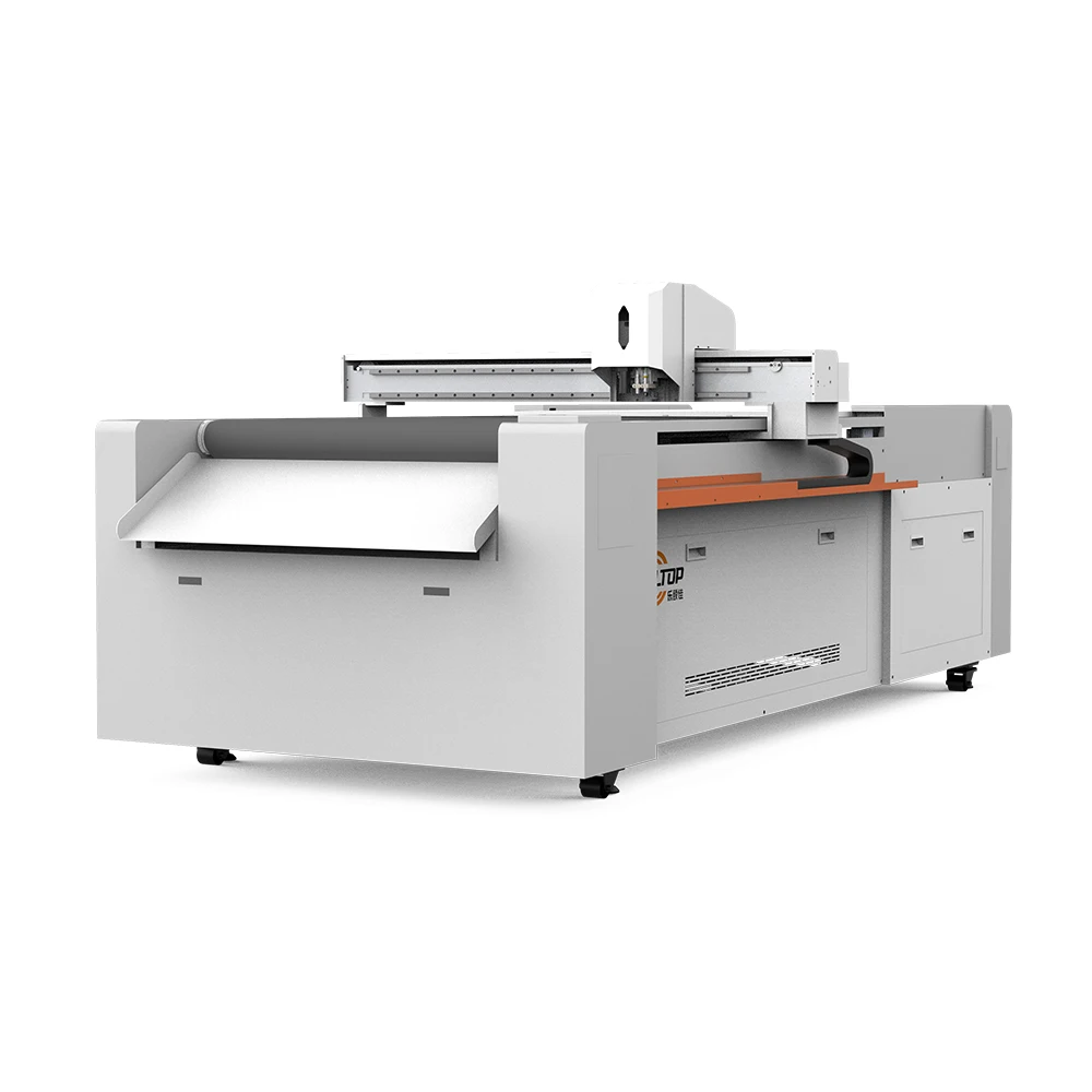
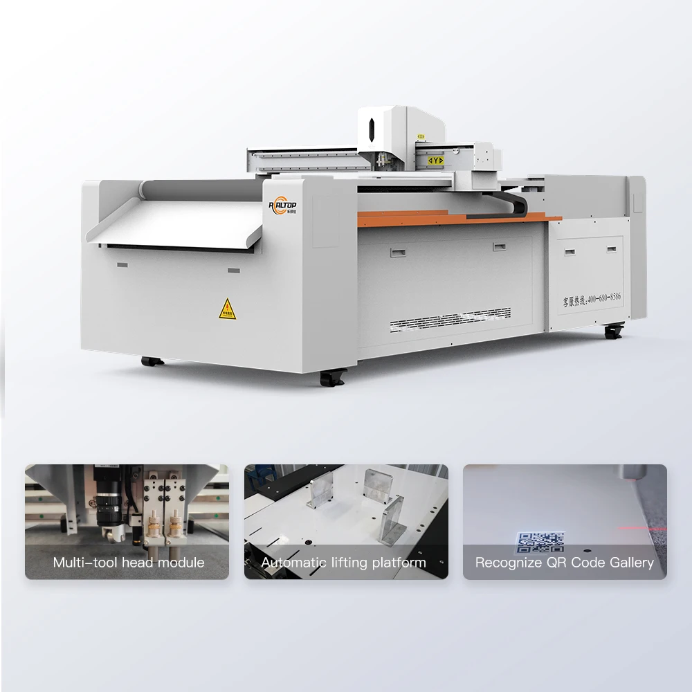
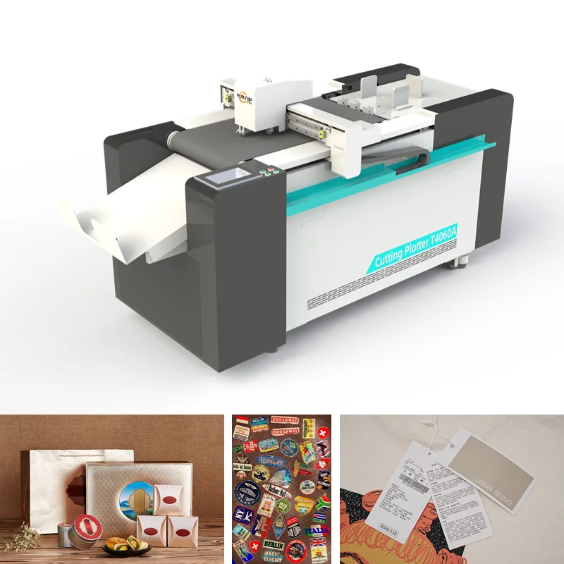
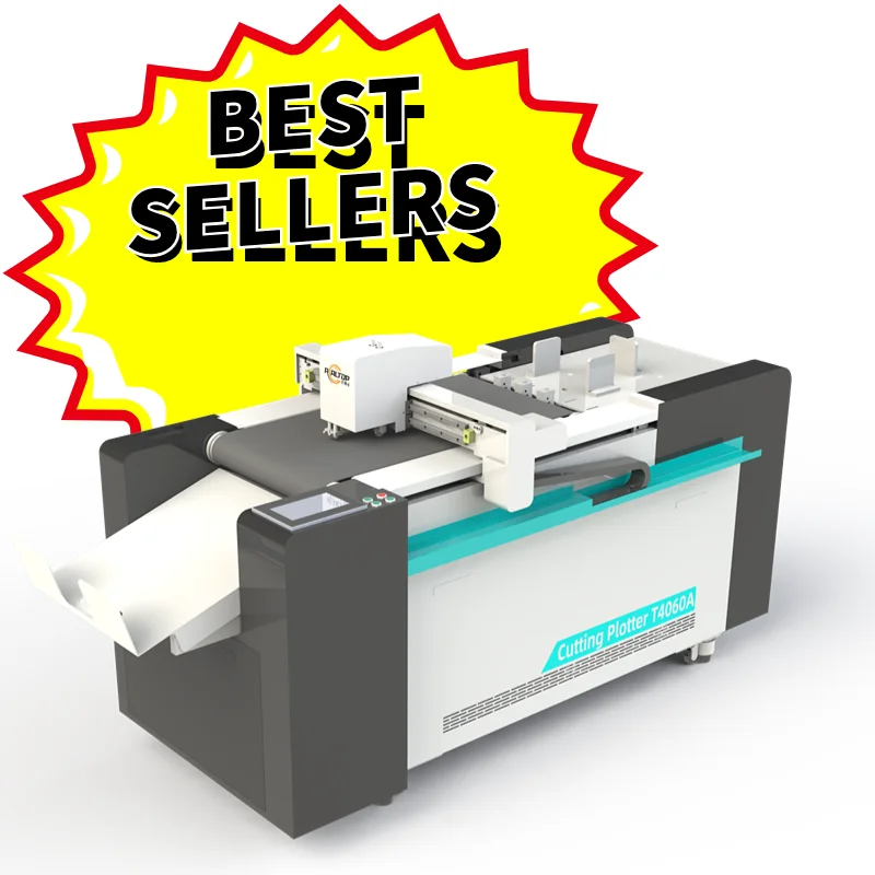
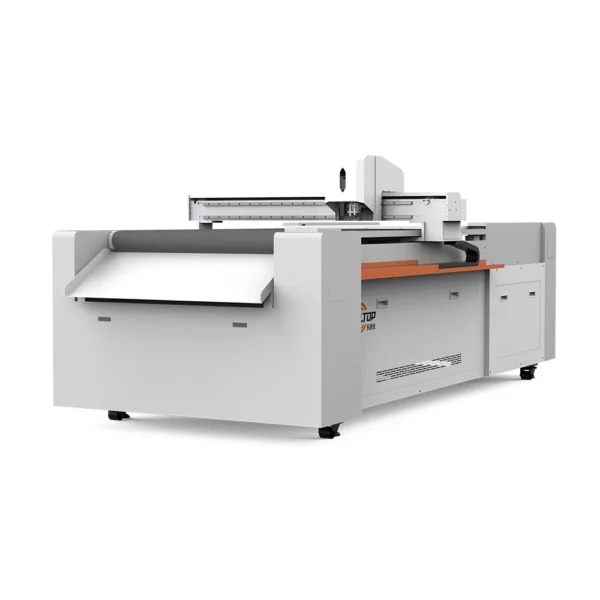
Multi-Tool Configuration on a Compact Footprint — the T-series matches oscillating knife, creasing wheel, and CCD camera to your actual material before order confirmation, not after delivery.
Technical Specifications
| Parameter | Value |
|---|---|
| Product Type | CNC Oscillating Knife Cutting Plotter |
| Model | T-series (4060 / 6080 / 0912) |
| Working Area | 400×600 mm / 600×800 mm / 900×1200 mm |
| Tool Head Options | Oscillating knife, creasing wheel, kiss cutting tool, CCD camera, marking pen |
| Cutting Speed | 0–1500 mm/s |
| Maximum Cutting Thickness | ≤ 20 mm |
| Cutting Accuracy | ±0.1 mm |
| Repeatability | ±0.1 mm |
| Positioning System | CCD camera with auto-recognition of registration marks |
| Vacuum Pump | 2.5 kW / 3.2 kW |
| Voltage Options | 110 V / 220 V |
| Supported File Formats | PLT, DXF, AI, PDF (one-click import) |
| Safety Devices | Infrared sensor and emergency stop |
| Language Options | English, Russian, Italian, Chinese (customizable) |
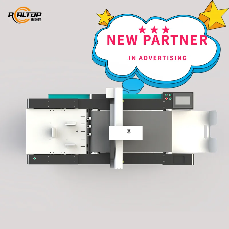
| Assembly State | Desktop structure, plug-and-play, no preheating required |
| Standards | CE |
Application Suitability
| Application | Material or Output |
|---|---|
| Packaging and carton sample making | Printed carton, cardboard, cardstock (≤2 mm) for prototyping and short runs |
| Advertising and graphics | Vinyl stickers, self-adhesive vinyl, PVC stickers, window clings, car decals |
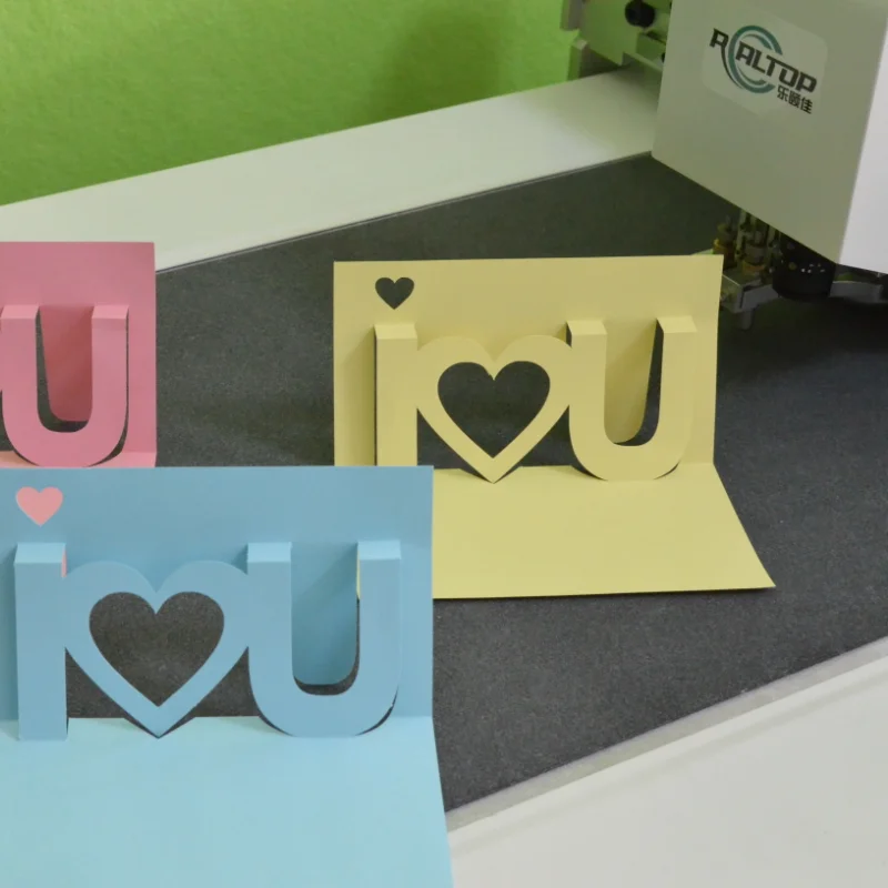
| Cultural and craft design | Leather bookmarks, custom paper-cut lamps, 3D greeting cards |
| Education and teaching aids | Puzzles, cards, science experiment templates |
| Light industry sampling | Electronic foam gaskets, packaging prototype sampling (1–50 pcs rapid small-batch) |
Why Working Area Alone Is Not Enough for CNC Oscillating Knife Cutting Plotter Specifications
A machine chosen by bed size often fails on the material it was supposed to cut.
I once saw a buyer specify a plotter purely by working area, then discover the tool head could not generate enough downforce on three-layer corrugated board with lamination. The spindle developed noise after months of strain, and the line stopped while waiting for replacement parts. The CNC oscillating knife cutting plotter specifications must cover the material stack, not just the sheet dimensions [NEED_CITE: common causes of tool head failure on laminated corrugated board]. When the tool head, vacuum zoning, and cutting pressure are matched to the actual stock before the order is placed, most field problems disappear.
Tool Head Selection by Material Type
The T-series offers oscillating knife, creasing wheel, kiss cutting tool, and marking pen on the same table. An oscillating knife handles corrugated cardboard and foam gaskets with clean vertical cuts, while the creasing wheel scores fold lines on cardstock without cracking the surface. The marking pen draws registration or assembly guides directly on the sheet. Selecting the correct head for each material is the single biggest factor in edge quality, and this CNC oscillating knife cutting plotter lets the operator switch heads between jobs rather than compromise with a single tool.
CCD Camera Contour Recognition for Printed Sheets
Printed carton and sticker jobs require the cutter to trace the exact contour of a pre-printed graphic. The CCD camera reads registration marks and adjusts the cutting path in real time, holding ±0.1 mm repeatability across the sheet. At production speed, the camera must track marks that shift slightly due to paper stretch or humidity — a factor that separates reliable contour cutting from scrap [NEED_CITE: print-to-cut registration accuracy in short-run packaging]. One-click import of AI and PDF files means the operator sends the design directly from the design suite without re-drawing contours.
Reading the Numbers Behind the Cutting Performance
The maximum cutting thickness of ≤20 mm covers single and double-wall corrugated board as well as foam gasket stock, but the actual usable thickness depends on material density and the tool head selected. Cutting speed reaches 0–1500 mm/s on straight runs, though intricate contour paths on printed vinyl will operate at lower speeds to maintain the ±0.1 mm accuracy. The 2.5 kW or 3.2 kW vacuum pump creates the hold-down force that keeps small sticker parts from lifting during the kiss cut — insufficient vacuum zoning is a frequent cause of mis-cut edges on small decals [NEED_CITE: vacuum table zoning requirements for small-format die-cutting]. Voltage availability in 110 V and 220 V means the plotter can be wired to match the local supply, confirmed before shipment to avoid transformer issues on site.
The Hidden Cost of Wrong Configuration Choices
When vacuum zoning is too broad for small sticker parts, the material lifts near the edges and the kiss cut drifts off the printed contour. When the creasing wheel is specified for thick corrugated but set to the wrong pressure, the score line cracks the top ply instead of folding cleanly. These failures do not show up in a factory test on sample stock — they appear weeks into production when the operator switches to the actual job material [NEED_CITE: field failures caused by vacuum table misconfiguration]. Catching the configuration gap before shipment is far less expensive than flying a technician across continents to re-commission the machine.
Why Source This Plotter from Realtop
The in-house design team covers both knife and laser cutting, so the cutting method is matched to the material rather than forced into one technology. Tool head and table configuration are specified per material type and daily volume, not quoted from a default list. CCD camera positioning for printed contour work is verified on the buyer’s own sheet before the machine leaves the factory. Software file format compatibility is confirmed during the order stage, eliminating workflow surprises at installation. Voltage, plug type, and control language are locked in on the electrical schematic before production starts.
Documentation & Verification
- Machine specification sheet listing the selected tool heads and working area configuration
- Electrical schematic confirming voltage, plug type, and circuit requirements for your facility
- Sample cutting report produced on your own cardboard, vinyl, or foam stock before dispatch
- CE declaration documentation covering the assembled desktop unit
- Software license and file format compatibility note for PLT, DXF, AI, and PDF workflows
Installation, Commissioning & Support
- Desktop plug-and-play design requires no foundation work or preheating cycle
- 110 V or 220 V power supply confirmed on the electrical schematic before shipment
- Vacuum pump commissioning includes zoning setup matched to your smallest part size
- CCD camera calibration performed on your printed registration marks during operator training
- Spare parts list covers oscillating knife blades, creasing wheels, and vacuum seals
- Operation manual and maintenance schedule provided in the selected control language
Preparing Your Inquiry
To receive a configuration that matches your production reality, share the material type and maximum thickness you cut most often, along with the typical sheet size and daily volume. Note your facility voltage and frequency, preferred control language, and whether your existing design files use AI, DXF, or PDF format. If you can send a sample of your printed stock or foam gasket material, a test cut can be arranged before you commit.
Frequently Asked Questions
Q: How is the correct tool head selected for my specific material type and thickness?
A: You provide a sample of your actual material — cardboard grade, vinyl thickness, or foam density — and the tool head is selected based on cutting force and edge quality requirements. A sample cutting report is produced on that material before the order is confirmed, so you can inspect edge finish and creasing accuracy directly.
Q: Can the CCD camera track printed registration marks reliably at full cutting speed?
A: The camera reads marks at production speed and holds ±0.1 mm repeatability. Performance depends on mark contrast and paper stability under humidity, so the camera is calibrated on your printed stock during the sample cutting stage to verify tracking accuracy before shipment.
Q: What voltage and plug configurations are available, and how is this confirmed?
A: The plotter is available in 110 V and 220 V. Your facility voltage and frequency are confirmed during the order stage, and the electrical schematic is issued showing the exact plug type and circuit requirements so no transformer or adapter is needed on arrival.
Q: Which file formats does the software support for my existing workflow?
A: The system imports PLT, DXF, AI, and PDF files through a one-click interface. File format compatibility with your design software and nesting workflow is verified before the order is placed, so operators can send jobs directly without file conversion.


商品评价
Clear filtersThere are no reviews yet.