



Fast Shipping
Carrier information

20k products
Payment methods

24/7 Support
Unlimited help desk

2-day Delivery
Track or off orders
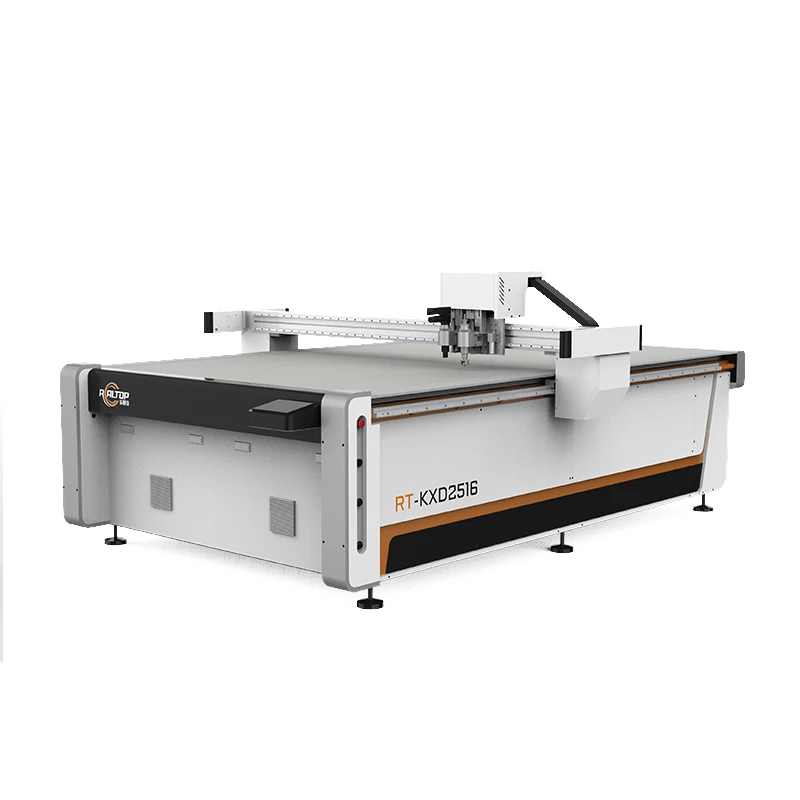
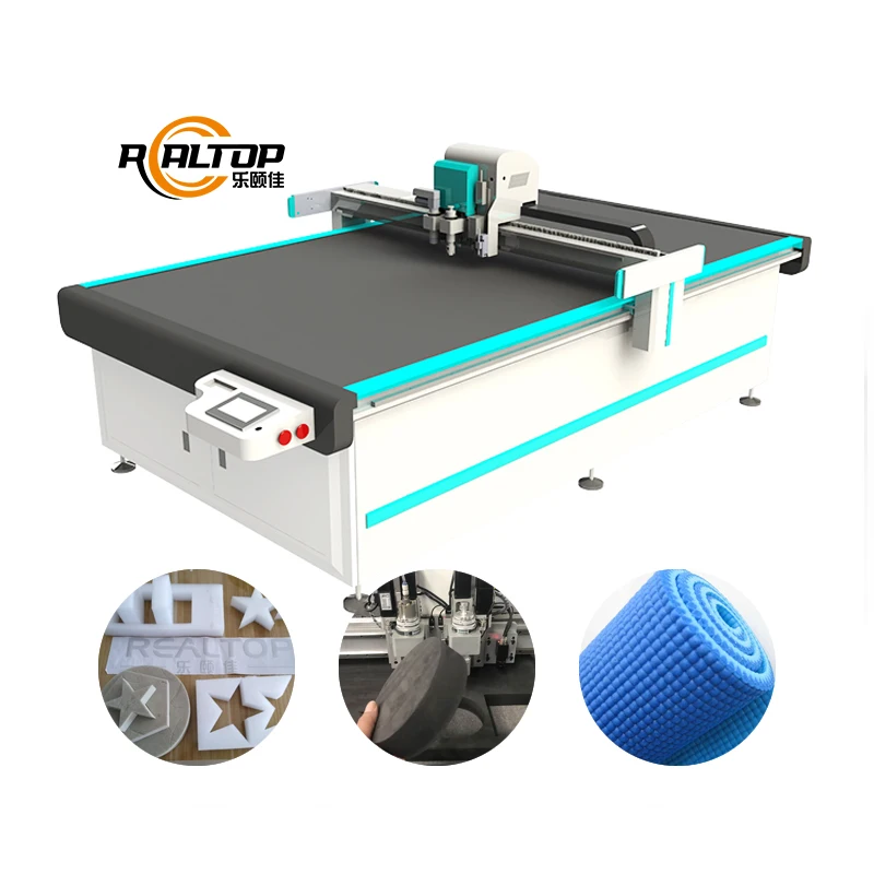
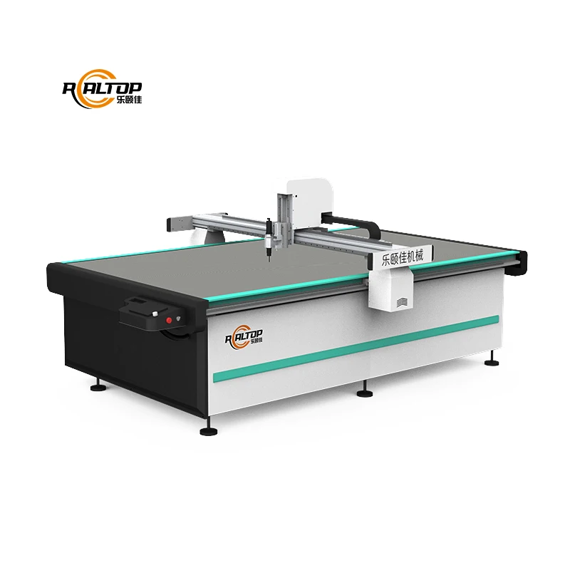
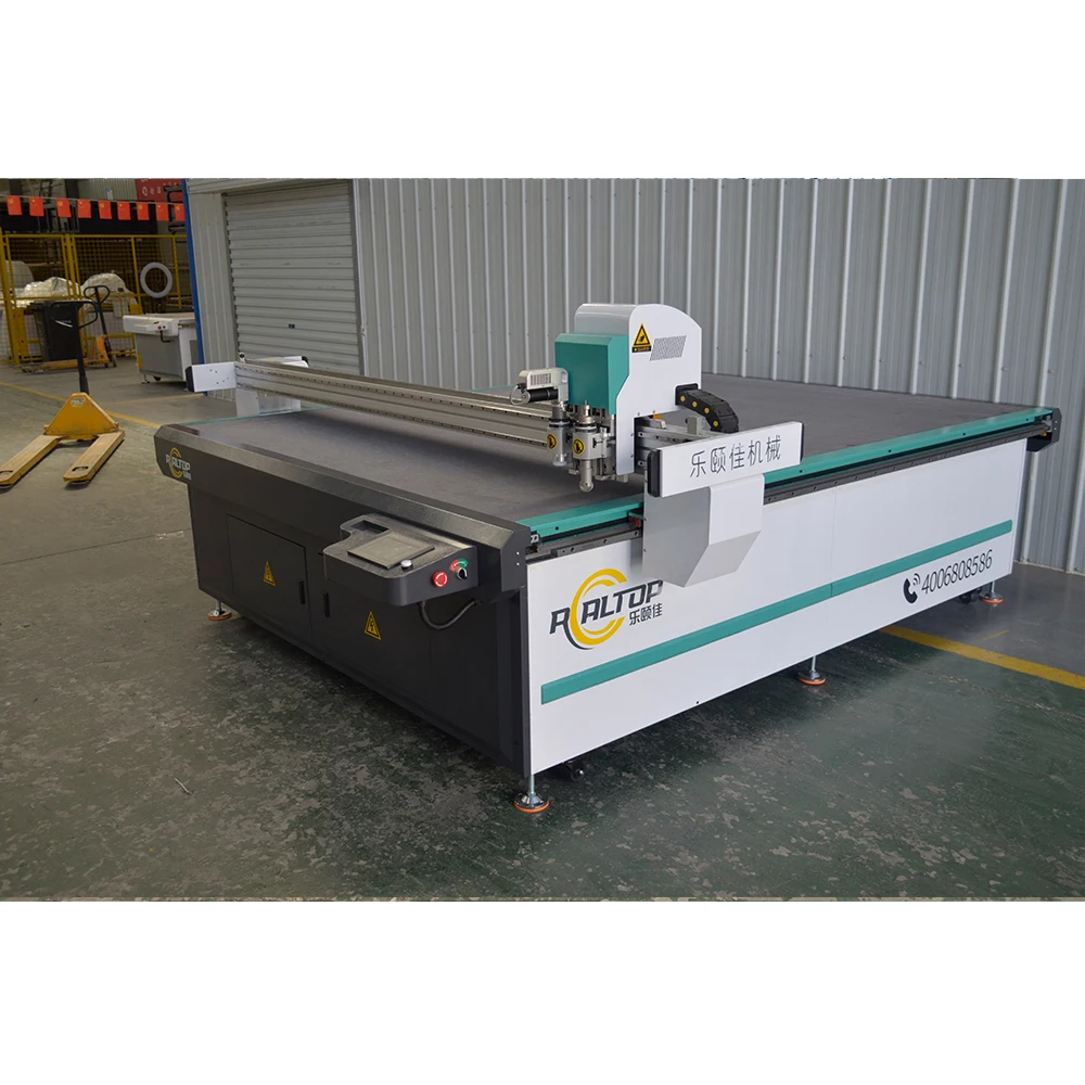
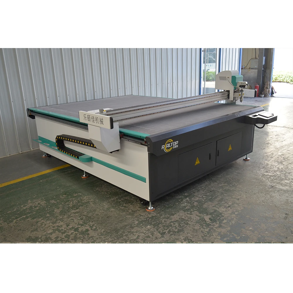
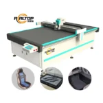
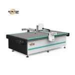
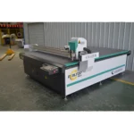
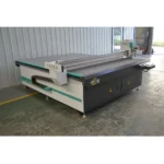
Tool Head and Table Configuration Specified per Material — the RT-D2516/RT-S2516 platform lets buyers match oscillating, drag or pneumatic knife options to composite, foam and automotive mat stacks rather than forcing a single cutting method across varying material densities.
Technical Specifications
| Parameter | Value |
|---|---|
| Model | RT-D2516/RT-S2516 |
| Product Type | CNC Oscillating Knife Cutting Machine |
| Working Area | 1600×2500 mm |
| Machine Size (Overall Dimensions) | 3450×2300×1250 mm |
| Rated Power | 9 kW |
| Voltage | 380V±10% |
| Tool Head | Multifunctional head with Swiss imported knife (vibration full cutting, vibration half cutting, cursor location) |
| Translational Velocity | 800–2000 mm/s |
| Repeated Accuracy | ≤0.1 mm |
| Transmission System | Digital servo motor (Delta or Panasonic optional), linear guide, synchronous belt, ball screw |
| Linear Rail | Taiwan Hiwin |
| Working Table | Magnesium-aluminum alloy vacuum adsorption table (PVDF powder sprayed, anodic oxidation, hard oxidation) |
| Vacuum Pump | 7.5 kW, integrated aviation aluminum shell with built-in silencer sponge |
| Conveyor | Germany imported conveyor belt, auto feeding |
| Safety Device | Infrared sensors, anti-collision on both sides of beam, emergency stop |
| Instruction System | HP-GL compatible format |
| Welded Frame | Thick-walled seamless steel structure, high-temperature tempering, CNC machining center finished |
| Software & File Formats | HP-GL compatible; nesting, layout and calculation system included |
| Certification | CE (unit-level certification to confirm) |
| Cutting Thickness | 200–800 mm/s (basis not stated in source — confirm material and thickness) |
| Cutting Speed Claim | 3–5 times faster than laser cutting machine (basis not stated in source — confirm material and format) |
Application Suitability
| Application | Material or Output |
|---|---|
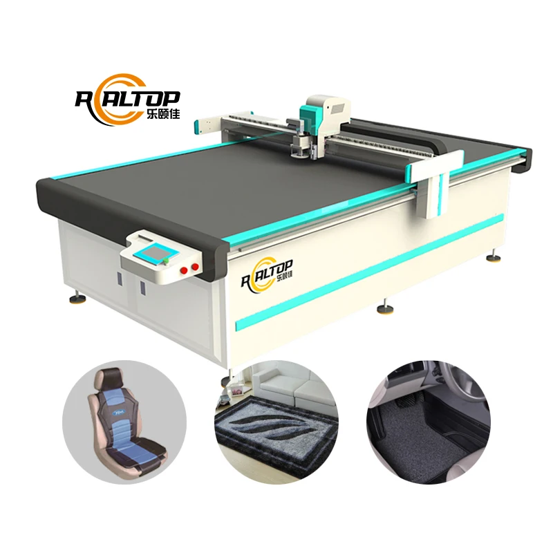
| Automotive interior and car mat production | Multi-layer composite mats, XPE/EVA foam, coil-backed materials on the 1.6×2.5 m bed |
| Leather, footwear and garment cutting | Natural and synthetic hides, layered textiles with CCD contour recognition on nested sheets |
| Gasket and composite fabrication | Sponge composite leather, PVC, silicon, rubber requiring burr-free edges without thermal damage |
| Packaging and carton sample making | Corrugated board, folding carton stock, foam inserts for protective packaging prototypes |
| Signage and vinyl production | Self-adhesive vinyl, reflective sheeting, flexible magnetic materials for display and vehicle graphics |
Why the Wrong Tool Head Ruins Your Composite Edge Quality
Selecting a CNC Oscillating Knife Cutting Machine based on working area alone, then discovering the blade cannot handle material density or abrasive content, is a frequent and costly misstep in composite cutting operations.
The tool head must be specified against the exact material stack, thickness and edge-quality requirement — not assumed from a general machine category.
I once configured a vibration knife cutter for a car mat producer who ran TPE samples without issue. When production switched to a glass-fiber-reinforced composite, blades degraded within days and throughput dropped sharply. The fix was not a new machine but a different tool head, blade geometry and oscillation frequency matched to the abrasive layer. Buyers evaluating flatbed digital cutting tables need to verify that the oscillating, drag or pneumatic knife option is selected on the basis of their actual production material, not the sample that happened to be on the desk during the demo [NEED_CITE: tool head selection criteria for abrasive composite materials].
Oscillation Mechanics and Composite Layer Integrity
The Swiss imported knife head on the RT-D2516/RT-S2516 supports vibration full cutting, vibration half cutting and cursor location within a single multifunctional assembly. Full oscillation drives the blade through dense, multi-layer composite stacks such as automotive floor mats where XPE foam, adhesive interlayers and coil backing must be severed cleanly in one pass. Half cutting scores kiss-cut depths on adhesive-backed materials without penetrating the release liner. Cursor location provides a physical reference point for manual alignment when CCD contour recognition is not required. Matching the oscillation mode to the specific composite structure is what separates a clean edge from a delaminated one.
Vacuum Hold-Down Across the 1600×2500 mm Bed
The magnesium-aluminum alloy table surface undergoes PVDF powder spraying, anodic oxidation and hard oxidation to maintain flatness under continuous vacuum load. A 7.5 kW vacuum pump with an integrated aviation aluminum shell and silencer sponge generates suction across the working area. For large automotive mat panels, full-bed adsorption keeps the material flat during high-speed contour cuts. For smaller gasket or footwear pattern pieces, zoning the vacuum into segments prevents air bleed from uncovered areas and stops thin composite sheets from lifting mid-cut. Insufficient zoning is one of the most common reasons small composite parts shift during oscillating knife passes [NEED_CITE: vacuum table zoning best practices for small-part CNC cutting].
Drive Precision and Contour Consistency
The Delta or Panasonic digital servo drive paired with Taiwan Hiwin linear rails holds repeated accuracy to ≤0.1 mm across the full travel range. In composite cutting, this tolerance matters most on long contour paths where accumulated positional drift produces mismatched nesting outlines. A car mat with a perimeter contour of several meters will show visible misalignment at the closure point if repeated accuracy drifts beyond the material’s acceptable seam allowance. The thick-walled seamless steel frame, finished on a CNC machining center after high-temperature tempering, resists deflection under the lateral forces generated when the oscillating knife engages dense composite stacks at translational velocities up to 2000 mm/s.
The Hidden Cost of Underspecifying Your Configuration
When vacuum zoning is not matched to the smallest part in a nesting layout, composite sheets lift at the edges and the oscillating knife tears rather than cuts, leaving ragged contours that fail visual inspection. When blade type is selected for a soft sample but the production material contains glass fiber or mineral filler, tool life shortens and unplanned blade changes interrupt the cutting cycle repeatedly. When voltage, plug type and control language are not confirmed before shipment, the machine sits idle on the factory floor while adapters and translations are arranged locally [NEED_CITE: common causes of CNC cutting machine commissioning delays]. Each of these gaps is avoidable if the specification conversation starts with the material rather than the working area.
Why Buyers Source This Platform for Composite Cutting
In-house design covers both knife and laser cutting technologies, so the buyer selects the cutting method by material behavior rather than being limited to one process. Tool head and table configuration are specified per material type, thickness and production volume, not left as a generic default. CCD camera positioning is available for printed contour work on nested hides and synthetic sheets where optical mark tracking must keep pace with production speed. Software compatibility with HP-GL format and nesting workflows is confirmed before order placement. Sample cutting runs on the buyer’s own material are conducted before commitment, providing edge quality and vacuum hold-down evidence specific to the composite stack in question.
Documentation & Verification
- Machine specification sheet listing tool head and table configuration matched to your composite material
- Electrical schematic with voltage, plug type and control language confirmed before shipment
- Sample cutting report on your own material verifying edge quality and hold-down performance
- Factory test record documenting repeated accuracy and contour closure on representative nesting layouts
- Software licence and file format compatibility note covering HP-GL and nesting workflow integration
- Spare parts list identifying blade types, vacuum seals and wearable components specific to your configuration
Installation, Commissioning & Support
- Floor space planning accounting for the 3450×2300 mm machine footprint plus operator and material access clearance
- Dedicated 380V±10% power circuit rated for 9 kW continuous load with appropriate breaker specification
- Assembled frame inspection after transit to verify high-temperature tempered steel structure alignment
- First-run vacuum zoning calibration on your actual composite sheet size to confirm hold-down uniformity
- Oscillation frequency and blade geometry tuning for your specific material stack during on-site commissioning
- Operator training covering HP-GL file import, nesting layout setup and tool head changeover procedures
Requesting a Quotation That Matches Your Production Reality
Provide the specific composite material type, layer structure and total stack thickness you intend to cut. Include your typical sheet dimensions, nesting layout complexity and daily volume target so the tool head and vacuum configuration can be sized accordingly. Specify your local voltage, frequency, plug standard and preferred control language to ensure the electrical and interface configuration is confirmed before the machine leaves the factory.
Frequently Asked Questions
Q: How do I choose between oscillating knife, drag knife and pneumatic knife heads for composite materials?
A: Oscillating knives suit thick, dense composite stacks such as automotive mats where full-depth vibration cutting produces clean edges through multiple layers. Drag knives handle thinner flexible sheets like vinyl or single-layer leather. Pneumatic knives address very thick foam or sponge where blade stroke must be adjustable. The correct choice depends on your material type, thickness and required edge finish. Request a sample cutting report on your own material to confirm.
Q: How should vacuum table zoning be configured for small versus large composite parts?
A: Large automotive mat panels use full-bed vacuum adsorption across the 1600×2500 mm working area. Small gasket or footwear pieces require segmented zoning so that uncovered areas do not bleed suction away from the parts being cut. The 7.5 kW pump must be matched to the zone configuration. Specify your smallest part size during the quotation stage so zoning is configured before build.
Q: How does CCD contour recognition perform at production speed on printed marks?
A: CCD camera positioning tracks printed registration marks on nested sheets to align the cutting path with pre-printed contours on composite materials. Performance depends on mark contrast, lighting conditions and the translational velocity setting. Confirm your print mark specification and nesting file format before order so the camera system can be calibrated to your actual production workflow.
Q: How can I verify cutting thickness and speed claims for my specific composite material?
A: The published cutting thickness and speed values are provided without a stated material basis. Request a sample cutting run on your own composite stack at the thickness and layer structure you intend to produce. The sample cutting report documents achievable depth, edge quality and cycle time specific to your material rather than a generic benchmark.
Q: What voltage, language and plug customization is confirmed before shipment?
A: The standard voltage is 380V±10%, but local voltage, frequency and plug type must be confirmed before production. Control language options are specified during the quotation stage. The electrical schematic, voltage confirmation document and plug specification are included in the documentation package shipped with the machine to prevent on-site rework during commissioning.


商品评价
Clear filtersThere are no reviews yet.