



Fast Shipping
Carrier information

20k products
Payment methods

24/7 Support
Unlimited help desk

2-day Delivery
Track or off orders
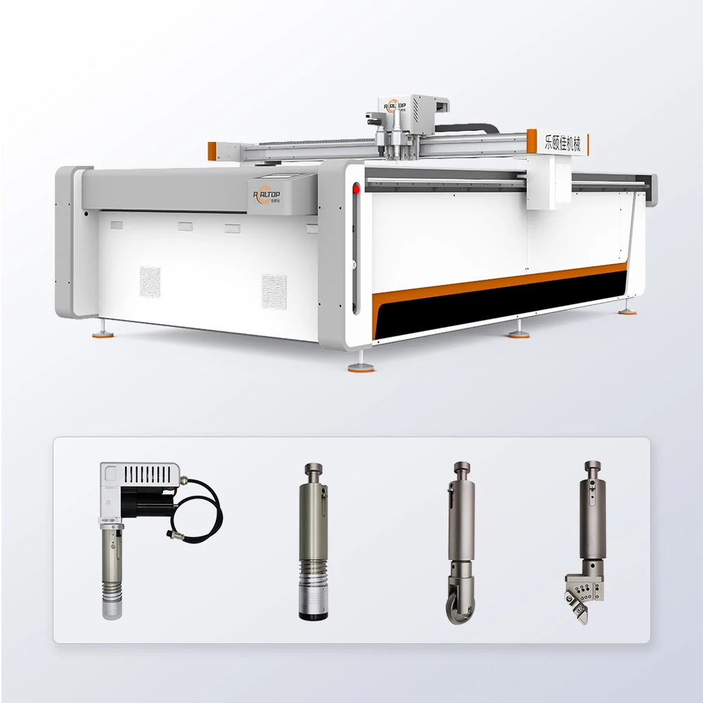
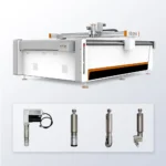
Tool head matched to material layup — oscillating, rotary, V-groove and kiss cutting tools specified per composite density and thickness before the machine is built, not selected from a generic catalog after the fact.
Technical Specifications
| Parameter | Value |
|---|---|
| Model | 1625(std.) |
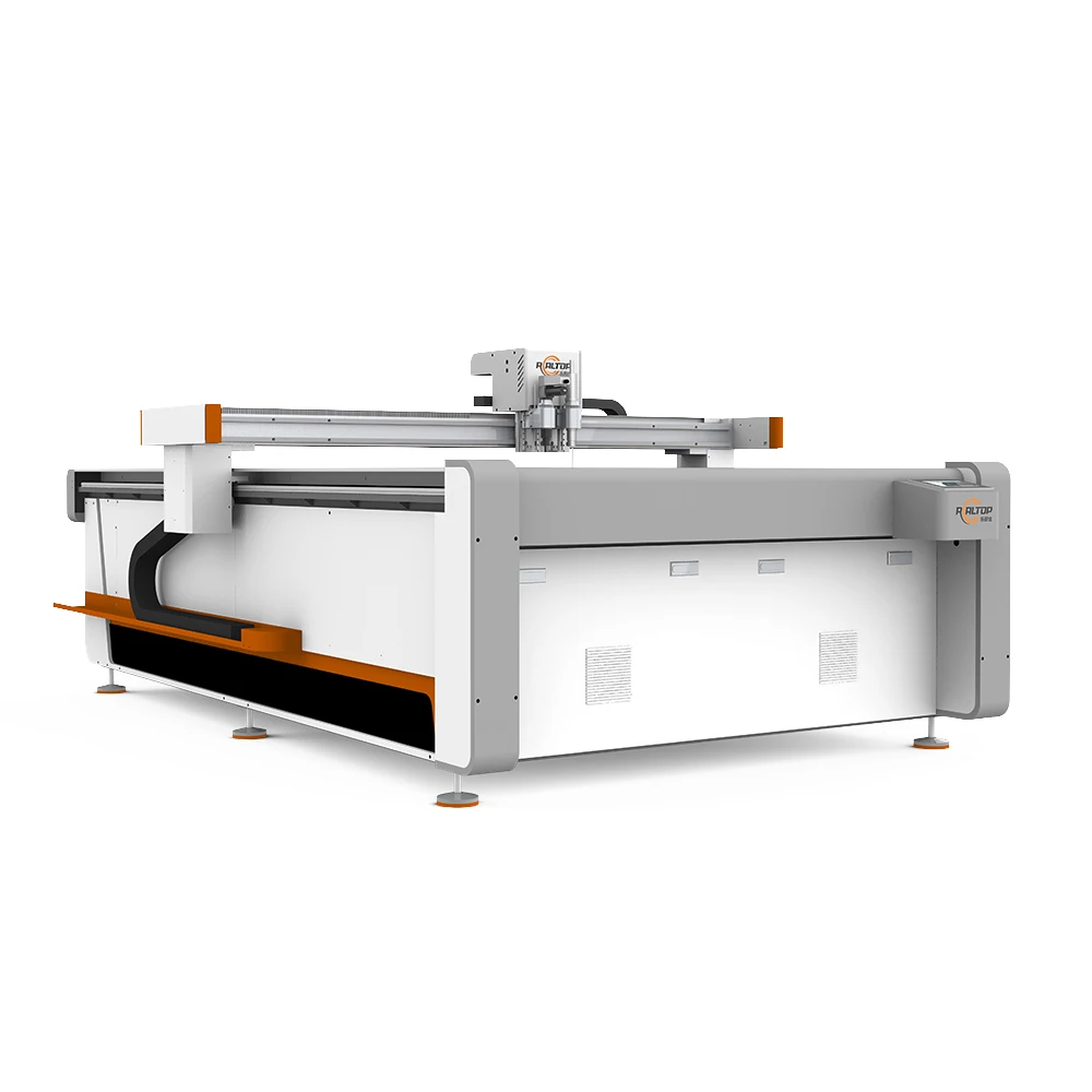
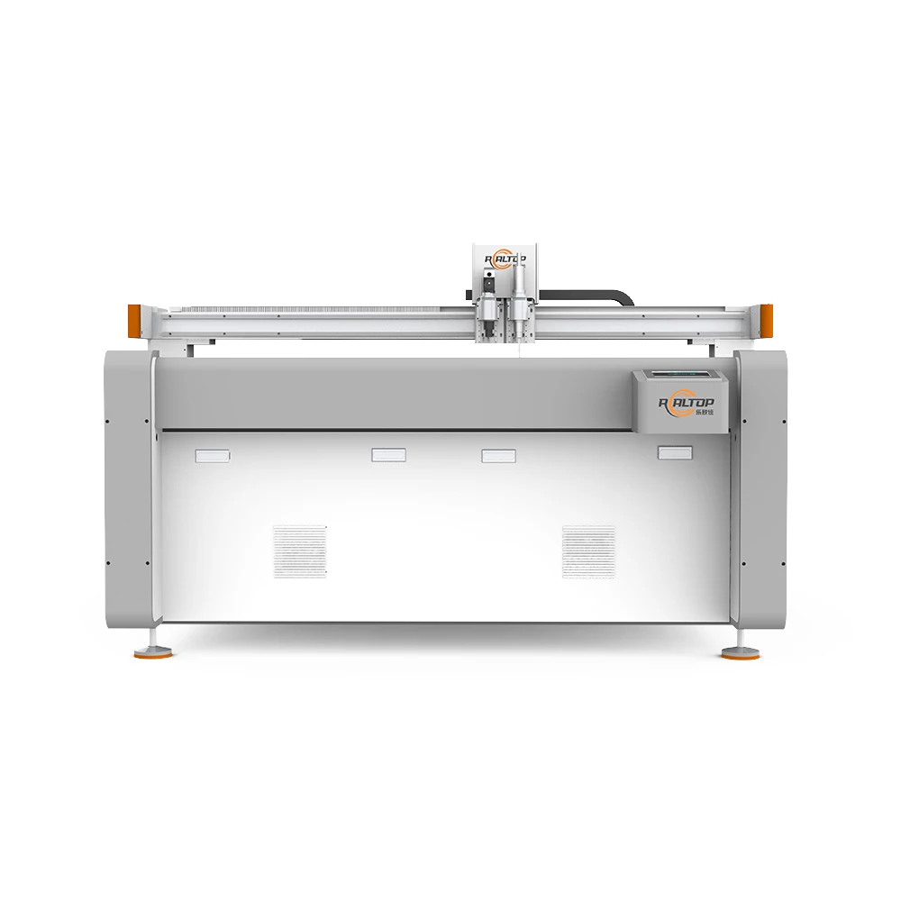
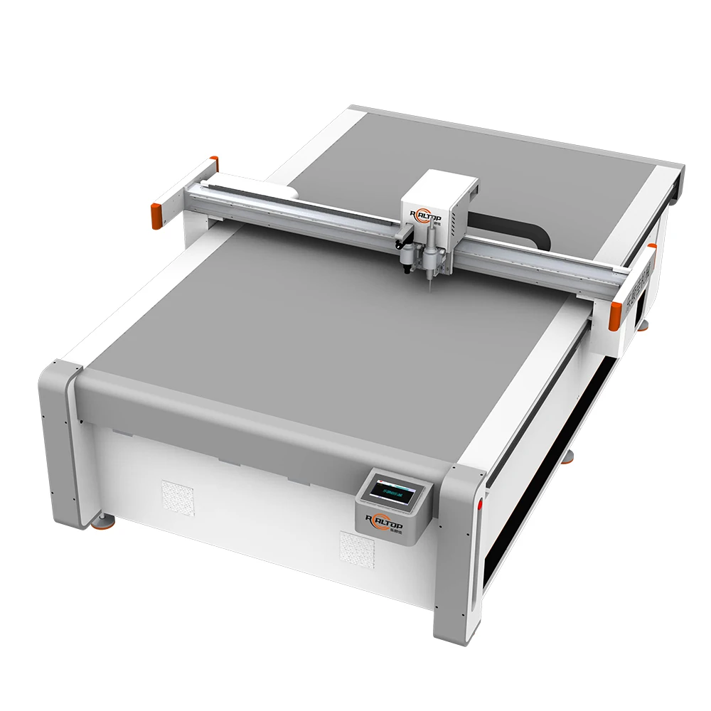
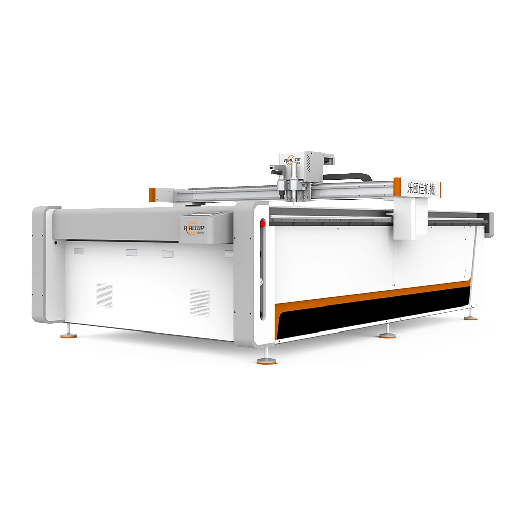
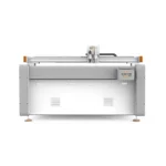
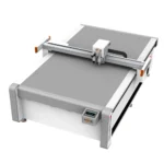
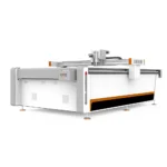
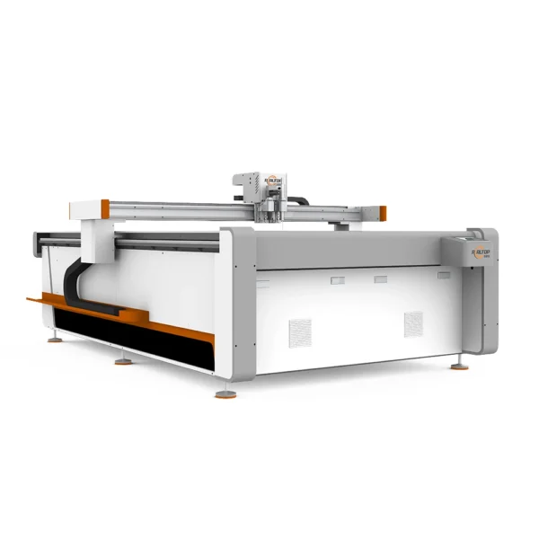
| Product Type | CNC Oscillating Knife Cutting Machine |
| Cutting Area | 1600 × 2500 mm |
| Tool Head Options | Oscillating knife, Driven rotary knife, Creasing wheel, Kiss cutting tool, Pneumatic knife, Milling tool, V groove knife |
| Cutting Speed | 0–1500 mm/s |
| Cutting Thickness | ≤ 40 mm (basis not stated in source) |
| Cutting Accuracy | ±0.1 mm |
| Vacuum Pump | 9 kW |
| Vacuum Table | Aluminum bellows vacuum table |
| Servo Motors | Panasonic, Delta, Dorna options |
| Control System | PLC control panel with optional display languages |
| Voltage | 110V, 220V, 380V (rated or peak not specified in source) |
| Profile Formats | PLT, DXF, AI, PDF |
| Safety Device | Infrared sensor device and emergency stop device |
| Machine Size | 3300 × 2100 × 1350 mm |
| Standards | CE |
Application Suitability
| Application | Material or Output |
|---|---|
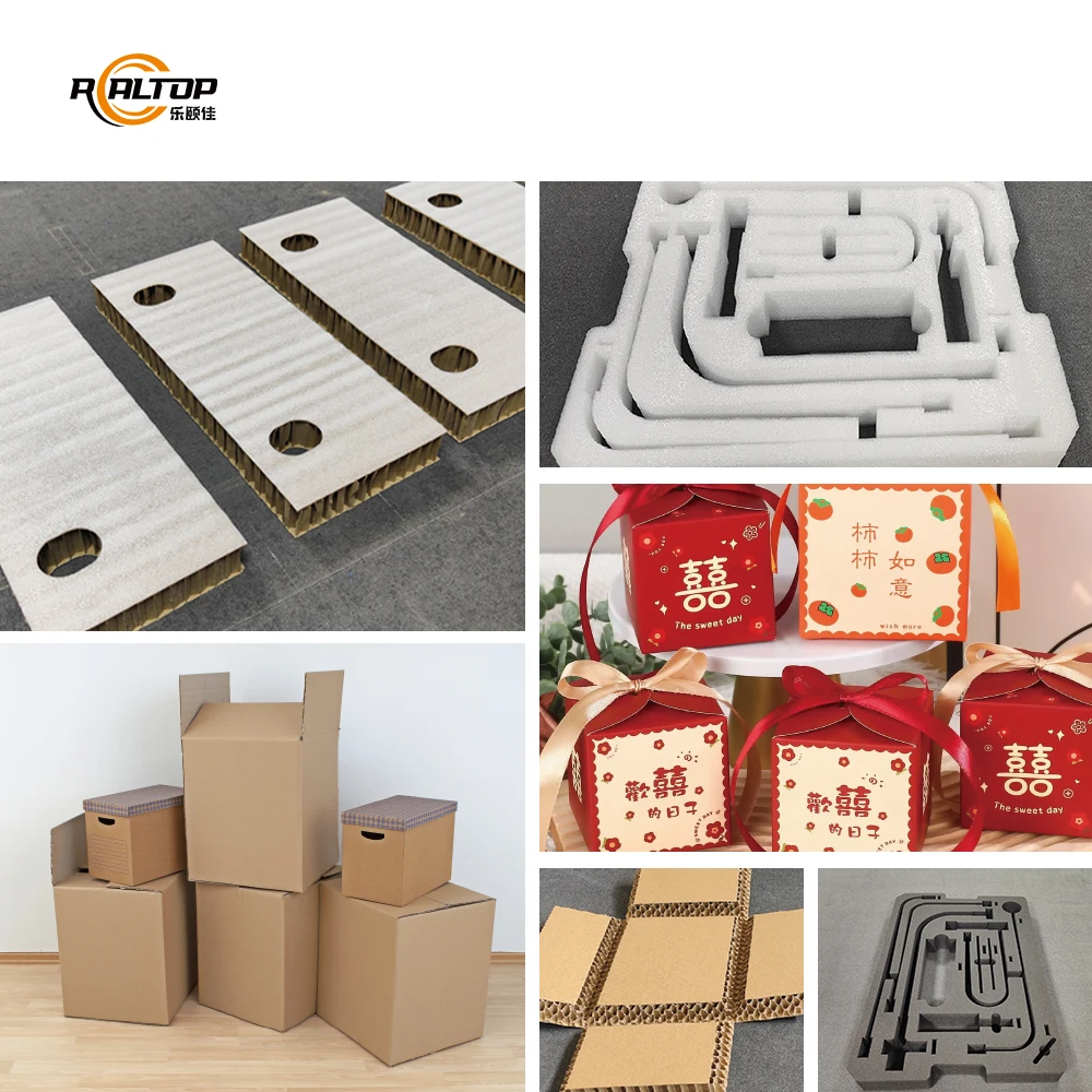
| Packaging sample making | Corrugated cardboard (E-flute, B-flute, BC-flute), greyboard, cardstock, art paper |
| Foam fabrication | EVA, EPE, PU foam sheets, layered adhesive-backed foam |
| Automotive interior and gasket cutting | Rubber mats, PTFE sheets, multi-layer composite gasket stock |
| Composite panel processing | Adhesive-backed composite laminates, thin PVC and PET sheets |
| Textile and leather cutting | Velvet, fleece, non-woven fabric, synthetic leather |
Why Oscillating Knife Cutter Specifications Alone Cannot Guarantee a Clean Edge
A machine spec sheet tells you what the frame can do; only a material-specific tool head and vacuum configuration tell you what the machine will actually cut on your shop floor.
I spent years on the assembly floor here in Jinan watching machines get built to working-area dimensions and shipped out, only to hear back weeks later that the customer’s composite material was delaminating at the cut line or the foam was crushing under the knife. The cutting thickness figure of ≤ 40 mm on a CNC oscillating knife cutter specifications sheet means very little without knowing whether that number came from a rigid PVC block or a multi-layer adhesive-backed foam stack. When a buyer specifies a machine based on table size alone and skips the material trial, the result is almost always the same: ragged edges on composites, crushed cells on foam, or delamination on layered gasket stock [NEED_CITE: material-specific cutting parameters for composite layups]. The tool head that slices cleanly through B-flute corrugated will tear right through a PTFE sheet if the oscillation frequency and blade angle are wrong for that polymer.
Matching Tool Head Geometry to Composite Structure
The 1625 model carries seven tool head options — oscillating knife, driven rotary, creasing wheel, kiss cutting, pneumatic knife, milling, and V-groove — and each one exists because a specific material behavior demands it. Oscillating knife handles rigid and semi-rigid composites where a clean shear cut prevents delamination between layers. Driven rotary suits continuous fabric and non-woven runs where the blade must follow curves without dragging. V-groove scoring on greyboard and corrugated packaging board sets the fold line without cutting through, something a standard oscillating blade cannot do in a single pass. Selecting the correct tool head is the single most important step in configuring a CNC oscillating knife cutter for composites and foam.
Vacuum Table Zoning and Small-Part Holding
Composites and foam share a frustrating trait: once a cut path releases a small part from the surrounding sheet, the vacuum can pull air through the kerf and the part lifts or shifts mid-cut. The aluminum bellows vacuum table on this machine provides a flat sealing surface that maintains suction across the 1600 × 2500 mm work area, but flatness alone does not solve the zoning problem. If the table has insufficient independent zones, a small gasket or packaging insert loses hold while the knife is still finishing adjacent geometry [NEED_CITE: vacuum zoning strategies for CNC flatbed cutting tables]. Proper zone configuration means the vacuum under uncut material stays sealed while the area around small finished parts is managed independently.
Reading the Specs That Actually Affect Your Cut Quality
The ±0.1 mm cutting accuracy figure matters most when you are nesting gasket profiles or packaging dielines where cumulative tolerance error throws off fold alignment downstream. The 9 kW vacuum pump rating determines how much suction reaches the table surface after accounting for line loss through hoses and fittings — undersized pumps show up as part drift on the last few cuts of a nested sheet, not the first. Servo motor selection across Panasonic, Delta, or Dorna affects acceleration behavior on tight corners; a motor that cannot decelerate fast enough will leave witness marks on foam at direction changes. The PLC control panel with optional display languages and support for PLT, DXF, AI, and PDF file imports means the machine can accept files directly from most packaging structure design and nesting software without intermediate conversion, reducing a step where geometry errors commonly enter the workflow.
What Happens When Configuration Is Skipped
I once configured a cutting table for a gasket manufacturer who sent a sample in standard asbestos board. We ran the trial, the edge was clean, and the machine shipped. Three weeks later the customer called — their actual production material was multi-layer composite rubber, denser and more abrasive, and the standard oscillating blade was producing frayed edges on every cut. The tool head that works on single-layer board will not necessarily hold an edge through composite stacks, and the vacuum zoning that holds a large sheet flat will not keep small die-cut inserts from lifting [NEED_CITE: common causes of edge quality failure in CNC knife cutting]. The cost of getting configuration wrong is never just a blade change; it is downtime, scrapped material, and lost production schedules while you re-spec the machine remotely.
Why This Configuration Approach Works Here
The design team and production floor operate in the same facility in Jinan, which means the person who selects your tool head can walk over to the test table and run your material before the build is finalized. Both knife tooling and table configuration are developed in-house rather than sourced from separate vendors, so the vacuum zoning and tool head selection are coordinated as one system. Sample cutting runs on the buyer’s own composite, foam, or corrugated stock before the order is confirmed, producing a documented cutting report that shows edge quality, dimensional accuracy, and recommended tooling. Software compatibility is verified against the buyer’s existing file formats and nesting workflow before the machine enters production. Voltage, plug type, and control language are confirmed against the destination market’s electrical standards, not left to assumption at the packing stage [NEED_CITE: voltage and frequency standards by export market].
Documentation & Verification
- Machine specification sheet listing confirmed tool head and table configuration for your material
- Electrical schematic with voltage and plug type matched to destination market
- Sample cutting report on buyer-supplied composite or foam stock with edge quality photos
- Tool head and vacuum zone configuration list tied to your production volume
- Software licence documentation with confirmed file format compatibility note
- CE declaration and factory test record covering full work-area travel
Installation, Commissioning & Support
- Floor space allocation for the 3300 × 2100 × 1350 mm machine footprint with access clearance for material loading
- Dedicated electrical circuit matching confirmed voltage (110V/220V/380V) and the 9 kW vacuum pump draw
- Assembly of aluminum bellows vacuum table and frame leveling on-site after transport
- First-run parameter tuning with your actual composite or foam material to set oscillation frequency and cutting speed
- PLC control panel language setup and operator training on tool head changeover procedures
- Spare parts list covering blades, oscillation mechanism wear parts, and vacuum table seals
What to Share Before Quoting
To build a configuration that holds up on your production floor, the starting point is your actual material — type, layer count, thickness, and sheet dimensions — along with the daily volume you need to sustain. Let us know your facility’s available voltage and frequency, the control panel language your operators need, and whether your existing nesting or packaging design software outputs PLT, DXF, AI, or PDF. If you can send a sample of your composite or foam stock, we will run a documented cutting trial before any commitment is made.
Frequently Asked Questions
Q: How do I choose between oscillating knife and driven rotary for my composite material?
A: Oscillating knife suits rigid and semi-rigid composites where a clean shear cut prevents layer separation. Driven rotary works better on flexible, continuous materials like fabric and non-woven where the blade must follow curves without pulling. The choice depends on your specific composite density and layer structure, which is why we run a sample cut on your material before confirming the tool head.
Q: Will small gasket parts lift off the table during cutting?
A: Small parts can lift if the vacuum table zoning does not isolate the cut area from surrounding sealed zones. The aluminum bellows table on the 1625 model provides a flat sealing surface, but the zone configuration must be matched to your typical part size and nesting pattern. We confirm the zoning layout based on your production geometry before the machine is built.
Q: What does the ≤ 40 mm cutting thickness actually apply to?
A: The published thickness figure is measured under specific material and layer conditions that are not stated in the source documentation. Cutting depth varies significantly between rigid PVC, multi-layer foam, and adhesive-backed composites. We establish the real cutting capacity for your material through a sample cutting trial and document the result before the order proceeds.
Q: Can this machine accept files from my existing nesting software?
A: The control system accepts PLT, DXF, AI, and PDF profile formats, which covers most packaging structure design and nesting platforms. We verify compatibility with your specific software output during the pre-order stage and include a file format compatibility note in the documentation. If your workflow uses a format outside this set, we identify the conversion step needed before production begins.
Q: How are voltage and control language confirmed before shipment?
A: Voltage options include 110V, 220V, and 380V configurations, and the PLC control panel supports multiple display languages. Both are confirmed against your facility’s electrical supply and operator requirements during the specification stage, documented in the electrical schematic, and verified during the factory test before packing.


商品评价
Clear filtersThere are no reviews yet.