






Fast Shipping
Carrier information

20k products
Payment methods

24/7 Support
Unlimited help desk

2-day Delivery
Track or off orders
Tool head selection matched to material — Every RT-D2516/RT-S2516 configuration is verified against your actual board grade, flute profile and thickness before the machine leaves our Jinan workshop.
Technical Specifications
| Parameter | Value |
|---|---|
| Model | RT-D2516/RT-S2516 |
| Working Area | 1600 × 2500 mm |
| Overall Dimensions | 3450 × 2300 × 1250 mm |
| Rated Power | 9 kW |
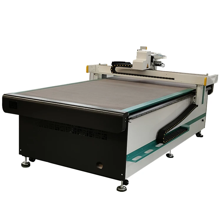
| Worktable Type | Flat vacuum table with 7.5 kW vacuum pump |
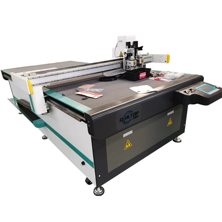
| Multifunctional Tool Head | Swiss imported knife with vibration full cutting, half cutting and cursor location |
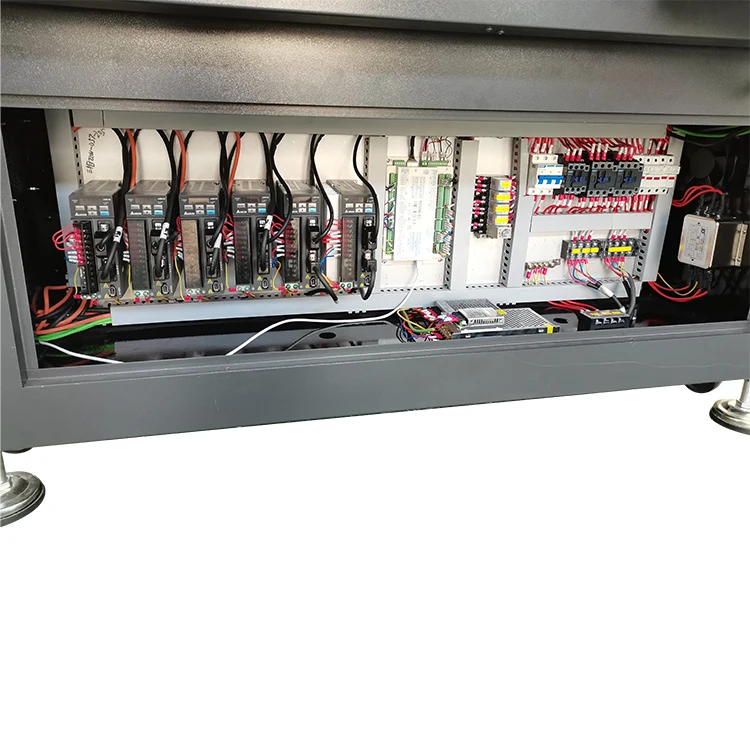
| Transmission System | Digital servo motor, linear guide, synchronous belt, imported ball screw |
| Servo Motor | Japanese Yaskawa |
| Linear Rail | Taiwan Hiwin |
| Repeated Accuracy | ≤ 0.1 mm |
| Translational Velocity | 800–1200 mm/s |
| Cutting Speed | 200–800 mm/s (varies by material type and thickness) |
| Pneumatic Cutting Tool Max Thickness | Up to 70 mm (basis to be confirmed) |
| Instruction System | HP-GL compatible format |
| Voltage | 380V ± 10% |
| Safety Device | Infrared sensors |
| Other Configuration | Germany imported conveyor belt, auto feeding |
| Machine Functions | Cutting, creasing and marking |
| Warranty | 12 months for the whole machine; 3 months for consumables |
| Standards | CE |
Application Suitability
| Application | Material or Output |
|---|---|
| Carton and packaging sample making | Corrugated board across common flute profiles |
| Box making industry | Rigid grey board and folding carton stock |
| Cardboard carton sample making | Multi-layer board for structural prototypes |
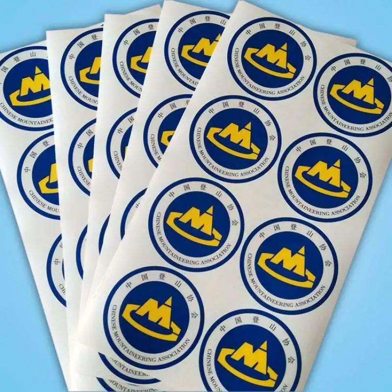
| Sticker and label sample production | Self-adhesive vinyl and flexible composite sheets |
| Gift box making | Thick grey board requiring clean creasing and scoring |
Why Working Area Alone Cannot Dictate Your CNC Oscillating Knife Cutting Table Specifications
The right CNC oscillating knife cutting table specifications depend on the material you actually cut, not just the sheet size you feed.
Too many packaging sample makers specify a flatbed cutter based purely on table dimensions, only to discover the machine cannot push through high-density grey board or handle the lateral forces of creasing thick corrugated stock. I saw this happen with an early customer who ordered the minimum configuration for a standard working area, then spent months fighting ragged edges and crushed flutes on heavy board grades. The tool head and vacuum zoning must be matched to your specific material stack before anything else is decided [NEED_CITE: importance of matching tooling to material density in digital cutting].
How Tool Head Configuration Determines Edge Quality on Board Stock
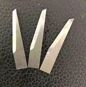
The Swiss imported knife on this table supports vibration full cutting and vibration half cutting, which is the difference between a clean through-cut on a corrugated prototype and a crushed, unusable edge. Vibration frequency and blade geometry must align with the board density you are running. On rigid grey board, insufficient oscillation leaves torn fibers at the exit point, while on thin flute corrugated, excessive vibration can delaminate the liner. Selecting the right oscillating knife cutting table specifications means defining which tool heads — drag knife, creasing wheel, oscillating knife — your production mix actually requires before the order is placed.
Vacuum Table Zoning and Small Carton Sample Hold-Down
A 7.5 kW vacuum pump paired with a flat working table provides the suction needed to hold full sheets of corrugated and grey board during high-speed traversal. However, the real challenge in packaging sample cutting appears when the job shifts to small carton components with limited surface area. Without proper zoning on the vacuum table, these small parts lift off the bed mid-cut, producing dimensional drift or tool strikes. The table configuration must account for the smallest piece in your typical sample set, not just the largest sheet you load [NEED_CITE: vacuum hold-down requirements for small-part CNC cutting].
Reading the Specs That Actually Matter for Packaging Work
The Japanese Yaskawa servo motors and Taiwan Hiwin linear rails directly influence the ≤ 0.1 mm repeated accuracy figure, which matters when you are cutting interlocking tab structures on carton samples where even slight deviation prevents proper assembly. The HP-GL compatible instruction system determines whether your existing CAD workflow can feed this machine without costly software conversion. The cutting speed range of 200–800 mm/s is material-dependent — expect the lower end on thick grey board and the upper range on thin corrugated or sticker stock. Understanding these CNC oscillating knife cutting table specifications in practical terms prevents the common mistake of comparing machines purely on headline speed numbers. The 380V ± 10% supply requirement must be confirmed against your workshop electrical infrastructure before installation planning begins.
The Hidden Cost of Underspecifying Your Cutting Table
When a packaging sample maker under-specifies the vacuum system or chooses a single-purpose tool head to save on initial outlay, the consequences surface within the first production quarter. Creasing wheels that cannot maintain consistent depth on variable board thickness produce box prototypes that fail structural testing. Insufficient vacuum zoning forces operators to tape down small parts manually, adding handling time to every sample run. I have seen operations where the wrong configuration turned a machine intended to accelerate sample turnaround into a bottleneck that required more manual finishing than the previous hand-method workflow [NEED_CITE: hidden costs of underspecified CNC cutting configurations].
What Our Jinan Workshop Builds Into Every Table
In-house design and production means we control the frame fabrication, motion component selection and tool head integration under one roof, rather than assembling bought-in modules. Every tool head and table configuration is specified against your material type and sample volume before the build begins, so you receive a machine matched to your actual production mix. CCD camera positioning is available for printed contour work where registration marks must be tracked at cutting speed. Software compatibility is confirmed with your existing file formats during the order stage, not discovered at commissioning. Sample cutting on your own board material runs before commitment, giving you a physical report on edge quality, creasing depth and dimensional accuracy before the machine enters production.
Documentation & Verification
- Machine specification sheet listing confirmed tool head and vacuum configuration
- Electrical schematic with 380V ± 10% supply verification for destination market
- Sample cutting report produced on your specific board grade and thickness
- Tool head and table configuration list matched to your material and volume
- Software licence and HP-GL file format compatibility note before dispatch
- Factory test record documenting accuracy and speed on representative packaging stock
Installation, Commissioning & Support
- Flat table footprint of 3450 × 2300 mm requires level concrete floor with adequate clearance
- 9 kW rated power demands dedicated circuit with 380V ± 10% supply confirmed on-site
- Machine ships with auto feeding conveyor belt and vacuum pump as integrated components
- First-run commissioning includes parameter setting for your specific board materials
- Operator training covers tool head changes between cutting, creasing and marking functions
- Spare parts list covers blades, creasing wheels and vacuum table consumables
What We Need to Specify Your Table Correctly
To recommend the right configuration, we need the specific board grades and flute profiles you cut most often, along with typical thickness ranges across your sample work. Tell us your daily sample volume and the smallest component size in your typical carton designs so we can configure vacuum zoning accordingly. Confirm your workshop voltage and frequency, your preferred control language, and whether your existing CAD files output in HP-GL format or require conversion.
Frequently Asked Questions
Q: How is cutting thickness verified for different board grades and flute profiles?
A: We run sample cuts on your actual board material before the order is confirmed. The sample cutting report documents edge quality, creasing depth and dimensional accuracy across the board grades you specify. This ensures the pneumatic cutting tool and oscillating knife configuration are matched to your real production thickness rather than a generic maximum figure.
Q: Does the vacuum table zoning hold small carton samples without lift at production speed?
A: The 7.5 kW vacuum pump on a flat working table provides strong hold-down for full sheets. For small carton components with limited surface area, vacuum zoning is configured during specification to match your smallest typical part size. This prevents material lift during high-speed traversal and maintains the ≤ 0.1 mm repeated accuracy across the cutting area.
Q: Can the software import my existing CAD file format and nesting workflow?
A: The instruction system supports HP-GL compatible format, which covers most packaging CAD platforms. We confirm file format compatibility and nesting workflow integration before the order is placed, providing a written compatibility note. If your current software outputs in a different format, we identify the conversion requirement during the specification stage.
Q: What tool head configuration is recommended for creasing versus full cutting on grey board?
A: Creasing on rigid grey board requires a dedicated creasing wheel with controlled depth, while full cutting uses the Swiss imported oscillating knife with vibration adjustment matched to board density. The multifunctional tool head on this machine supports both operations, and the specific combination is configured based on your sample cutting test results before shipment.
Q: Is CCD camera contour recognition available for printed registration marks on packaging samples?
A: CCD camera positioning is available as a configuration option for printed contour work. If your packaging samples include pre-printed graphics that require contour-following cuts, we specify the camera system during the order stage and verify mark recognition on your printed stock during the factory test before dispatch.


商品评价
Clear filtersThere are no reviews yet.